Infiniti FX35, FX50 (S51). Manual — part 811

P010A MANIFOLD ABSOLUTE PRESSURE SENSOR
EC-785
< DTC/CIRCUIT DIAGNOSIS >
[VK50VE]
C
D
E
F
G
H
I
J
K
L
M
A
EC
N
P
O
10.
DETECT MALFUNCTIONING PART
Check the following.
• Harness for open or short between battery current sensor and ECM
>> Repair open circuit, short to ground or short to power in harness or connectors.
11.
CHECK MANIFOLD ABSOLUTE PRESSURE (MAP) SENSOR INPUT SIGNAL CIRCUIT FOR OPEN
AND SHORT
1.
Check the continuity between manifold absolute pressure (MAP) sensor harness connector and ECM har-
ness connector.
2.
Also check harness for short to ground and short to power.
Is the inspection result normal?
YES
>> GO TO 13.
NO
>> GO TO 12.
12.
DETECT MALFUNCTIONING PART
Check the following.
• Harness for open or short between manifold absolute pressure (MAP) sensor and ECM
>> Repair open circuit, short to ground or short to power in harness or connectors.
13.
CHECK MANIFOLD ABSOLUTE PRESSURE (MAP) SENSOR
EC-785, "Component Inspection"
Is the inspection result normal?
YES
>> GO TO 14.
NO
>> Replace battery negative cable assembly.
14.
CHECK INTERMITTENT INCIDENT
GI-36, "Intermittent Incident"
.
>> INSPECTION END
Component Inspection
INFOID:0000000005610754
1.
CHECK MAP SENSOR-I
1.
Turn ignition switch OFF.
2.
Start engine and warm it up to normal operating temperature.
3.
Turn ignition switch OFF, wait at least 5 seconds and then turn ON.
4.
Check the voltage between ECM harness connector terminals as follows.
NOTE:
• To avoid the influence of intake manifold vacuum, check the voltage 1 or more minutes past after engine
is stopped.
• Because the sensor is absolute pressure sensor, output value may differ depending on atmospheric
pressure and altitude.
5.
Measure the atmospheric pressure.
Manifold absolute pressure (MAP) sensor
ECM
Continuity
Connector
Terminal
Connector
Terminal
F65
2
F111
69
Existed
ECM
+
–
Connector
Terminal
Connector
Terminal
F111
69
F111
70

EC-786
< DTC/CIRCUIT DIAGNOSIS >
[VK50VE]
P010A MANIFOLD ABSOLUTE PRESSURE SENSOR
NOTE:
As the atmospheric pressure described on the synoptic chart is the value at sea level, compensate the
pressure with the following chart.
6.
Check the manifold absolute pressure sensor value corresponding to the atmospheric pressure.
Is the inspection result normal?
YES
>> GO TO 2.
NO
>> Replace MAP sensor.
2.
CHECK MAP SENSOR-II
1.
Start engine and let it idle.
2.
Check intake manifold vacuum.
3.
Check the voltage between ECM harness connector terminals as per the following.
4.
Confirm the difference of the voltage when engine is stopped and at idling is within the values shown in
the following chart.
Is the inspection result normal?
YES
>> INSPECTION END
NO
>> Replace MAP sensor.
Altitude (m)
Compensated pressure (hPa)
0
0
200
-24
400
-47
600
-70
800
-92
1000
-114
1500
-168
2000
-218
Atmospheric pressure (hPa)
Voltage (V)
800
3.1 – 3.7
850
3.3 – 3.9
900
3.5 – 4.1
950
3.8 – 4.3
1000
4.0 – 4.6
1050
4.2 – 4.8
JMBIA0870GB
ECM
+
–
Connector
Terminal
Connector
Terminal
F111
69
F111
70
Intake manifold vacuum [kPA (mmHg)]
Voltage difference (V)
-40 (-300)
1.5 – 2.0
-53.3 (-400)
2.0 – 2.6
-66.7 (-500)
2.6 – 3.2
-80 (-600)
3.2 – 3.8
P0112, P0113 IAT SENSOR
EC-787
< DTC/CIRCUIT DIAGNOSIS >
[VK50VE]
C
D
E
F
G
H
I
J
K
L
M
A
EC
N
P
O
P0112, P0113 IAT SENSOR
Description
INFOID:0000000005237263
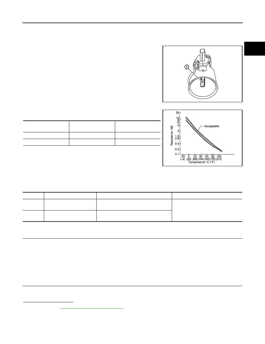
The intake air temperature sensor is built-into the mass air flow sen-
sor (1). The sensor detects intake air temperature and transmits a
signal to the ECM.
The temperature sensing unit uses a thermistor which is sensitive to
the change in temperature. Electrical resistance of the thermistor
decreases in response to the rise in temperature.
<Reference data>
*: These data are reference values and are measured between ECM terminals 48
(Intake air temperature sensor) and 42 (Sensor ground).
DTC Logic
INFOID:0000000005237264
DTC DETECTION LOGIC
DTC CONFIRMATION PROCEDURE
1.
PRECONDITIONING
If DTC Confirmation Procedure has been previously conducted, always perform the following procedure
before conducting the next test.
1.
Turn ignition switch OFF and wait at least 10 seconds.
2.
Turn ignition switch ON.
3.
Turn ignition switch OFF and wait at least 10 seconds.
>> GO TO 2.
2.
PERFORM DTC CONFIRMATION PROCEDURE
1.
Turn ignition switch ON and wait at least 5 seconds.
2.
Check 1st trip DTC.
Is 1st trip DTC detected?
YES
>> Go to
NO
>> INSPECTION END
PBIA9559J
Intake air temperature
[
°
C (
°
F)]
Voltage*
(V)
Resistance
(k
Ω
)
25 (77)
3.3
1.800 - 2.200
80 (176)
1.2
0.283 - 0.359
SEF012P
DTC No.
Trouble diagnosis name
DTC detecting condition
Possible cause
P0112
Intake air temperature sensor
circuit low input
An excessively low voltage from the sensor
is sent to ECM.
• Harness or connectors
(The sensor circuit is open or shorted.)
• Intake air temperature sensor
P0113
Intake air temperature sensor
circuit high input
An excessively high voltage from the sensor
is sent to ECM.

EC-788
< DTC/CIRCUIT DIAGNOSIS >
[VK50VE]
P0112, P0113 IAT SENSOR
Diagnosis Procedure
INFOID:0000000005237265
1.
CHECK GROUND CONNECTION
1.
Turn ignition switch OFF.
2.
Check ground connection M95. Refer to Ground Inspection in
Is the inspection result normal?
YES
>> GO TO 2.
NO
>> Repair or replace ground connection.
2.
CHECK INTAKE AIR TEMPERATURE SENSOR POWER SUPPLY CIRCUIT
1.
Disconnect mass air flow (MAF) sensor (bank 1) (intake air temperature sensor is built-in) harness con-
nector.
2.
Turn ignition switch ON.
3.
Check the voltage between MAF sensor (bank 1) harness connector and ground.
Is the inspection result normal?
YES
>> GO TO 3.
NO
>> Repair open circuit, short to ground or short to power in harness or connectors.
3.
CHECK INTAKE AIR TEMPERATURE SENSOR GROUND CIRCUIT FOR OPEN AND SHORT
1.
Turn ignition switch OFF.
2.
Disconnect ECM harness connector.
3.
Check the continuity between MAF sensor (bank 1) harness connector and ECM harness connector.
4.
Also check harness for short to ground and short to power.
Is the inspection result normal?
YES
>> GO TO 4.
NO
>> Repair open circuit, short to ground or short to power in harness or connectors.
4.
CHECK INTAKE AIR TEMPERATURE SENSOR
EC-788, "Component Inspection"
Is the inspection result normal?
YES
>> GO TO 5.
NO
>> Replace mass air flow sensor (bank 1) (with intake air temperature sensor).
5.
CHECK INTERMITTENT INCIDENT
GI-36, "Intermittent Incident"
>> INSPECTION END
Component Inspection
INFOID:0000000005237266
1.
CHECK INTAKE AIR TEMPERATURE SENSOR
1.
Turn ignition switch OFF.
2.
Disconnect mass air flow sensor (bank 1) harness connector.
3.
Check resistance between mass air flow sensor (bank 1) terminals as per the following.
MAF sensor (bank 1)
Ground
Voltage (V)
Connector
Terminal
F86
2
Ground
Approx. 5
MAF sensor (bank 1)
ECM
Continuity
Connector
Terminal
Connector
Terminal
F86
1
F110
42
Existed
Нет комментариевНе стесняйтесь поделиться с нами вашим ценным мнением.
Текст