Infiniti FX35, FX50 (S51). Manual — part 809

P0102, P0103, P010C, P010D MAF SENSOR
EC-777
< DTC/CIRCUIT DIAGNOSIS >
[VK50VE]
C
D
E
F
G
H
I
J
K
L
M
A
EC
N
P
O
*: Check for linear voltage rise in response to engine being increased to approximately 4,000 rpm.
Is the inspection result normal?
YES
>> INSPECTION END
NO
>> Clean or replace malfunctioning mass air flow sensor.
ECM
Condition
Voltage (V)
Connector
+
–
Terminal
Terminal
F110
47
[MAF sensor
(bank 1) signal]
42
Ignition switch ON (Engine stopped.)
Approx. 0.4
Idle (Engine is warmed-up to normal operating tem-
perature.)
0.8 - 1.1
2,500 rpm (Engine is warmed-up to normal operating
temperature.)
1.3 - 1.6
Idle to approx. 4,000 rpm
0.8 - 1.1 to approx. 2.4*
43
[MAF sensor
(bank 2) signal]
38
Ignition switch ON (Engine stopped.)
Approx. 0.4
Idle (Engine is warmed-up to normal operating tem-
perature.)
0.8 - 1.1
2,500 rpm (Engine is warmed-up to normal operating
temperature.)
1.3 - 1.6
Idle to approx. 4,000 rpm
0.8 - 1.1 to approx. 2.4*
EC-778
< DTC/CIRCUIT DIAGNOSIS >
[VK50VE]
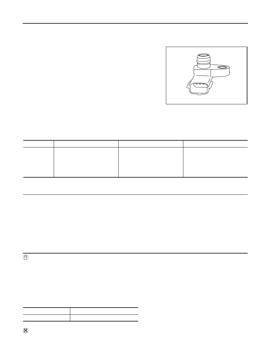
P0106 MANIFOLD ABSOLUTE PRESSURE SENSOR
P0106 MANIFOLD ABSOLUTE PRESSURE SENSOR
Description
INFOID:0000000005589035
The manifold absolute pressure (MAP) sensor is placed at intake
manifold collector. It detects intake manifold pressure and sends the
voltage signal to the ECM.
The sensor uses a silicon diaphragm which is sensitive to the
change in pressure. As the pressure increases, the voltage rises.
DTC Logic
INFOID:0000000005598019
DTC DETECTION LOGIC
NOTE:
If DTC P0106 is displayed with other DTC, first perform the trouble diagnosis for other DTC.
DTC CONFIRMATION PROCEDURE
1.
PRECONDITIONING
If DTC Confirmation Procedure has been previously conducted, always perform the following procedure
before conducting the next test.
1.
Turn ignition switch OFF and wait at least 10 seconds.
2.
Turn ignition switch ON.
3.
Turn ignition switch OFF and wait at least 10 seconds.
If engine will not start or stops soon, wait at least 10 seconds with engine stopped (Ignition switch ON) instead
of running engine at idle speed.
>> GO TO 2.
2.
PERFORM DTC CONFIRMATION PROCEDURE
With CONSULT-III
1.
Turn ignition switch ON and select “DATA MONITOR” mode with CONSULT-III.
2.
Start engine and warm it up to normal operating temperature.
3.
Accelerate the vehicle from 0 to 88 km/h (0 to 55 MPH) under the following conditions:
CAUTION:
Always drive at a safe speed.
NOTE:
• Accelerate with the accelerator pedal kept constant.
• The acceleration at engine speed 2,000 and 3,000 rpm allows easy diagnoses.
4.
Check 1st trip DTC.
Without CONSULT-III
1.
Start engine and warm it up to normal operating temperature.
JMBIA0877ZZ
DTC No.
Trouble diagnosis name
DTC detecting condition
Possible cause
P0106
Manifold absolute pressure (MAP)
circuit range/performance
A difference exceeding the specified
value develops between a value
transmitted from the manifold abso-
lute pressure (MAP) sensor to ECM
and an estimated intake pressure of
intake manifold calculated by ECM.
• Harness or connectors
(The sensor circuit is open or
shorted.)
• manifold absolute pressure (MAP)
sensor
• Intake air leaks
ACCEL SEN 1
1.4 – 2.0 V
Selector lever
D position

P0106 MANIFOLD ABSOLUTE PRESSURE SENSOR
EC-779
< DTC/CIRCUIT DIAGNOSIS >
[VK50VE]
C
D
E
F
G
H
I
J
K
L
M
A
EC
N
P
O
2.
Drive the vehicle under the following conditions.
3.
With selector lever in D position, accelerate the vehicle from 0 to 88 km/h (0 to 55 MPH) under the follow-
ing conditions:
CAUTION:
Always drive at a safe speed.
NOTE:
• Accelerate with the accelerator pedal kept constant.
• The acceleration at engine speed 2,000 and 3,000 rpm allows easy diagnoses.
4.
Check 1st trip DTC.
Is 1st trip DTC detected?
YES
>> Go to
NO
>> INSPECTION END
Diagnosis Procedure
INFOID:0000000005589037
1.
CHECK INTAKE SYSTEM
Check the following for connection.
• Air duct
• Vacuum hoses
• Intake air passage between air duct and intake manifold.
Is the inspection result normal?
YES
>> GO TO 2.
NO
>> Repair or replace ground connection.
2.
CHECK GROUND CONNECTION
1.
Turn ignition switch OFF.
2.
Check ground connection M95. Refer to Ground Inspection in
Is the inspection result normal?
YES
>> GO TO 3.
NO
>> Repair or replace ground connection.
3.
CHECK MANIFOLD ABSOLUTE PRESSURE (MAP) SENSOR POWER SUPPLY CIRCUIT CIRCUIT FOR
OPEN AND SHORT
1.
Disconnect manifold absolute pressure (MAP) sensor harness connector.
2.
Turn ignition switch ON.
3.
Check the voltage between manifold absolute pressure (MAP) sensor harness connector and ground.
Is the inspection result normal?
YES
>> GO TO 4.
NO
>> Repair open circuit, short to ground or short to power in harness or connectors.
4.
CHECK MANIFOLD ABSOLUTE PRESSURE (MAP) SENSOR GROUND CIRCUIT FOR OPEN AND
SHORT
1.
Turn ignition switch OFF.
2.
Disconnect ECM harness connector.
3.
Check the continuity between manifold absolute pressure (MAP) sensor harness connector and ECM har-
ness connector.
Accelerator pedal position sensor 1
Ground
Voltage (V)
Connector
Terminal
E112
3
Ground
1.4 – 2.0
Manifold absolute pressure (MAP) sensor
Ground
Voltage (V)
Connector
Terminal
F65
1
Ground
Approx. 5

EC-780
< DTC/CIRCUIT DIAGNOSIS >
[VK50VE]
P0106 MANIFOLD ABSOLUTE PRESSURE SENSOR
4.
Also check harness for short to ground and power.
Is the inspection result normal?
YES
>> GO TO 5.
NO
>> Repair open circuit, short to ground or short to power in harness or connectors.
5.
CHECK MANIFOLD ABSOLUTE PRESSURE (MAP) SENSOR INTPUT SIGNAL CIRCUIT FOR OPEN
AND SHORT
1.
Check the continuity between manifold absolute pressure (MAP) sensor harness connector and ECM har-
ness connector.
2.
Also check harness for short to ground and power.
Is the inspection result normal?
YES
>> GO TO 6.
NO
>> Repair open circuit, short to ground or short to power in harness or connectors.
6.
CHECK MANIFOLD ABSOLUTE PRESSURE (MAP) SENSOR
EC-780, "Component Inspection"
Is the inspection result normal?
YES
>> GO TO 7.
NO
>> Replace manifold absolute pressure (MAP) sensor.
7.
CHECK INTERMITTENT INCIDENT
GI-36, "Intermittent Incident"
>> INSPECTION END
Component Inspection
INFOID:0000000005589038
1.
CHECK MAP SENSOR-I
1.
Turn ignition switch OFF.
2.
Start engine and warm it up to normal operating temperature.
3.
Turn ignition switch OFF, wait at least 5 seconds and then turn ON.
4.
Check the voltage between ECM harness connector terminals as follows.
NOTE:
• To avoid the influence of intake manifold vacuum, check the voltage 1 or more minutes past after engine
is stopped.
• Because the sensor is absolute pressure sensor, output value may differ depending on atmospheric
pressure and altitude.
5.
Measure the atmospheric pressure.
NOTE:
As the atmospheric pressure described on the synoptic chart is the value at sea level, compensate the
pressure with the following chart.
Manifold absolute pressure (MAP) sensor
ECM
Continuity
Connector
Terminal
Connector
Terminal
F65
3
F111
70
Existed
Manifold absolute pressure (MAP) sensor
ECM
Continuity
Connector
Terminal
Connector
Terminal
F65
2
F111
69
Existed
ECM
+
–
Connector
Terminal
Connector
Terminal
F111
69
F111
70
Нет комментариевНе стесняйтесь поделиться с нами вашим ценным мнением.
Текст