Infiniti FX35, FX50 (S51). Manual — part 945
EM-80
< REMOVAL AND INSTALLATION >
[VQ35HR]
OIL SEAL
1.
Remove the following parts:
• Engine undercover with power tool.
• Drive belt: Refer to
• Crankshaft pulley: Refer to
.
2.
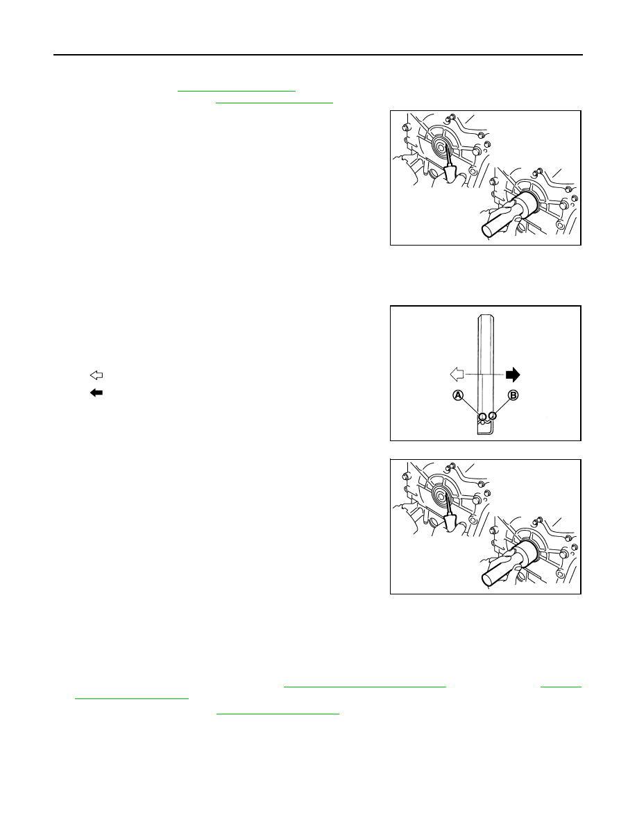
Remove front oil seal using a suitable tool.
CAUTION:
Be careful not to damage front timing chain case and crank-
shaft.
INSTALLATION
1.
Apply new engine oil to both oil seal lip and dust seal lip of new front oil seal.
2.
Install front oil seal.
• Install front oil seal so that each seal lip is oriented as shown in
the figure.
• Using a suitable drift, press-fit until the height of front oil seal is
level with the mounting surface.
- Suitable drift: outer diameter 60 mm (2.36 in), inner diameter
50 mm (1.97 in).
• Check the garter spring is in position and seal lips are not
inverted
CAUTION:
• Be careful not to damage front timing chain case and
crankshaft.
• Press-fit straight and avoid causing burrs or tilting oil
seal.
3.
Install in the reverse order of removal after this step.
REAR OIL SEAL
REAR OIL SEAL : Removal and Installation
INFOID:0000000005245154
REMOVAL
1.
Remove transmission assembly. Refer to
(2WD models) or
(AWD models).
2.
Remove drive plate. Refer to
.
3.
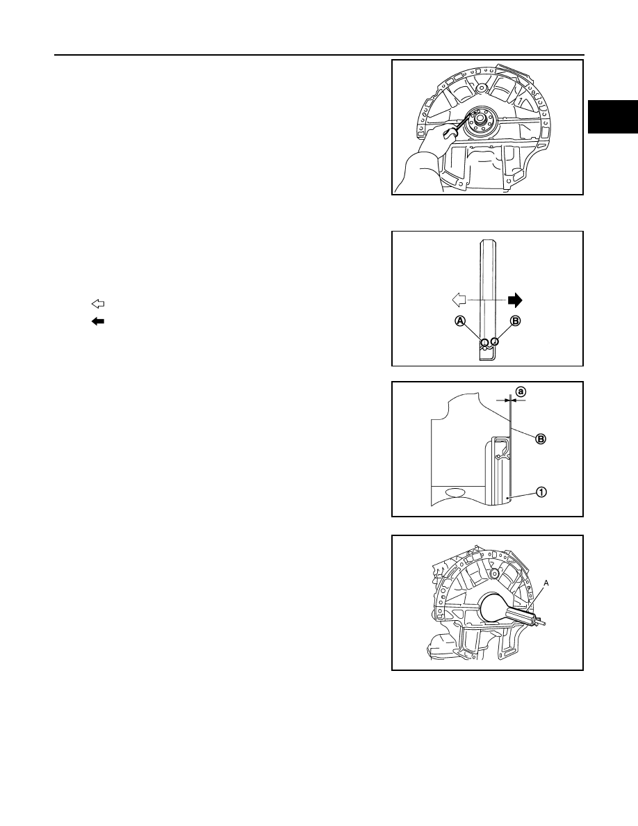
Remove rear oil seal with a suitable tool.
CAUTION:
PBIC2931E
A
: Oil seal lip
B
: Dust seal lip
: Engine inside
: Engine outside
JPBIA0054ZZ
PBIC2931E
OIL SEAL
EM-81
< REMOVAL AND INSTALLATION >
[VQ35HR]
C
D
E
F
G
H
I
J
K
L
M
A
EM
N
P
O
Be careful not to damage crankshaft and cylinder block.
INSTALLATION
1.
Install rear oil seal.
• Install rear oil seal so that each seal lip is oriented as shown in
the figure.
• Press in rear oil seal (1) to the position as shown in the figure.
• Using a suitable drift (A), press-fit until the height of rear oil seal is
level with the mounting surface.
- Suitable drift: outer diameter 100 mm (3.94 in), inner diameter 85
mm (3.35 in).
CAUTION:
• Be careful not to damage crankshaft and cylinder block.
• Press-fit straight and avoid causing burrs or tilting oil seal.
2.
Install in the reverse order of removal after this step.
PBIC2932E
A
: Oil seal lip
B
: Dust seal lip
: Engine inside
: Engine outside
JPBIA0054ZZ
B
: Cylinder block rear end face
a
: 0 - 0.5 mm (0 - 0.020 in)
JPBIA0152ZZ
JPBIA0153ZZ
EM-82
< UNIT REMOVAL AND INSTALLATION >
[VQ35HR]
ENGINE ASSEMBLY
UNIT REMOVAL AND INSTALLATION
ENGINE ASSEMBLY
2WD
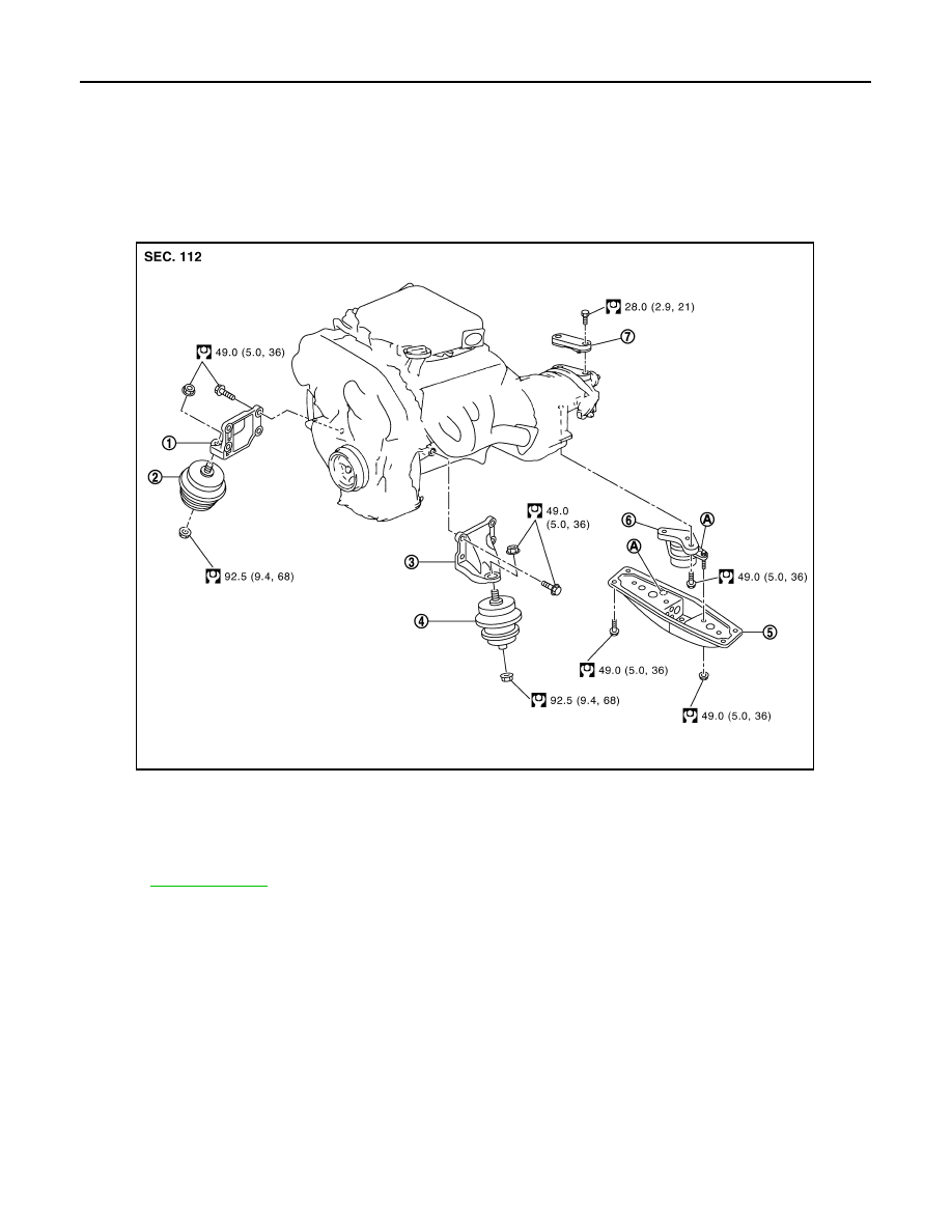
2WD : Exploded View
INFOID:0000000005245155
2WD : Removal and Installation
INFOID:0000000005245156
WARNING:
• Situate the vehicle on a flat and solid surface.
• Place chocks at front and back of rear wheels.
• For engines not equipped with engine slingers, attach proper slingers and bolts described in PARTS
CATALOG.
CAUTION:
• Always be careful to work safely, avoid forceful or uninstructed operations.
• Never start working until exhaust system and engine coolant are cool enough.
• If items or work required are not covered by the engine section, refer to the applicable sections.
• Always use the support point specified for lifting.
• Use either 2-pole lift type or separate type lift as best you can. If board-on type is used for unavoid-
able reasons, support at rear axle jacking point with transmission jack or similar tool before starting
work, in preparation for the backward shift of center of gravity.
1.
Engine mounting bracket (RH)
2.
Engine mounting insulator (RH)
3.
Engine mounting bracket (LH)
4.
Engine mounting insulator (LH)
5.
Rear engine mounting member
6.
Engine mounting insulator (rear)
7.
Dynamic damper
A.
Front mark
for symbols in the figure.
JPBIA0528GB

ENGINE ASSEMBLY
EM-83
< UNIT REMOVAL AND INSTALLATION >
[VQ35HR]
C
D
E
F
G
H
I
J
K
L
M
A
EM
N
P
O
• For supporting points for lifting and jacking point at rear axle, refer to
REMOVAL
Outline
At first, remove the engine and the transmission assembly with front suspension member downward. Then
separate the engine from transmission.
Preparation
1.
Release fuel pressure. Refer to
.
2.
Disconnect both battery cables. Refer to
.
3.
Drain engine coolant from radiator. Refer to
.
CAUTION:
• Perform this step when engine is cold.
• Never spill engine coolant on drive belt.
4.
Remove the following parts:
• Radiator reservoir tank: Refer to
• Engine cover: Refer to
• Front road wheel and tires (power tool)
• Engine undercover (power tool)
• Front cross bar: Refer to
• Cowl top cover: Refer to
.
• Air duct and air cleaner case assembly: Refer to
5.
Discharge refrigerant from A/C circuit. Refer to
HA-25, "Collection and Charge"
6.
Remove radiator hoses (upper and lower). Refer to
.
Engine Room LH
1.
Disconnect heater hose from vehicle-side, and fit a plug onto hose end to prevent engine coolant leakage.
2.
Disconnect A/C piping from A/C compressor, and temporarily fasten it on vehicle with a rope. Refer to
3.
Disconnect brake booster vacuum hose.
4.
Disconnect ground cable.
Engine Room RH
1.
Disconnect battery positive cable at vehicle side and temporarily fasten it on engine.
2.
Disconnect all clips and connector of the engine room harness from engine back side.
3.
Disconnect fuel feed hose (with damper) and EVAP hose. Refer to
CAUTION:
Fit plugs onto disconnected hoses to prevent fuel leakage.
4.
Remove reservoir tank of power steering oil pump and piping from vehicle, and temporarily secure them
on engine. Refer to
ST-48, "VQ35HR : Exploded View"
.
CAUTION:
When temporarily securing, keep the reservoir tank upright to avoid a fluid leakage.
Vehicle Inside
Follow procedure below to disconnect engine room harness connectors at passenger room side, and tempo-
rarily secure them on engine.
1.
Remove passenger-side kicking plate and dash side finisher. Refer to
.
2.
Disconnect engine room harness connectors at unit sides and other.
3.
Disengage intermediate fixing point. Pull out engine room harnesses to engine room side, and temporarily
secure them on engine.
CAUTION:
• When pulling out harnesses, take care not to damage harnesses and connectors.
• After temporarily securing, cover connectors with vinyl or similar material to protect against for-
eign material adhesion.
Vehicle Underbody
1.
Remove A/T fluid cooler hoses and power steering oil pump oil cooler hoses.
Нет комментариевНе стесняйтесь поделиться с нами вашим ценным мнением.
Текст