Infiniti FX35, FX50 (S51). Manual — part 967
EM-168
< PERIODIC MAINTENANCE >
[VK50VE]
SPARK PLUG
3.
Remove spark plug with a spark plug wrench (commercial ser-
vice tool).
INSTALLATION
Installation is the reverse order of removal.
Inspection
INFOID:0000000005245216
INSPECTION AFTER REMOVAL
Use the standard type spark plug for normal condition.
CAUTION:
• Never drop or impact spark plug.
• Never use a wire brush for cleaning.
• If plug tip is covered with carbon, use spark plug cleaner to
clean.
• Measure spark plug gap. When it exceeds the limit, replace spark plug even if it is within the speci-
fied replacement mileage. Refer to
• Spark plug gap adjustment is not required between replace-
ment intervals.
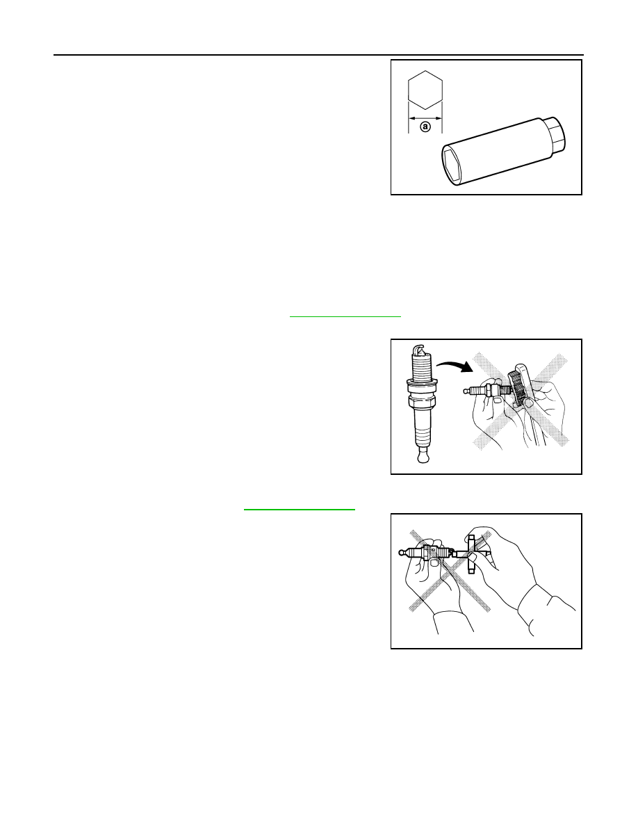
a
: 14 mm (0.55 in)
JPBIA0030ZZ
Spark plug (Standard type)
: Refer to
Cleaner air pressure
: Less than 588 kPa (6 kg/cm
2
, 85 psi)
Cleaning time
: Less than 20 seconds
SMA773C
JPBIA0031ZZ
CAMSHAFT VALVE CLEARANCE
EM-169
< PERIODIC MAINTENANCE >
[VK50VE]
C
D
E
F
G
H
I
J
K
L
M
A
EM
N
P
O
CAMSHAFT VALVE CLEARANCE
Inspection
INFOID:0000000005245217
INSPECTION
Check valve clearance if applicable to the following cases:
Intake side:
• At the removal and installation of VVEL ladder assembly or valve-related parts, or at the occurrence of mal-
function (poor starting, idle malfunction, unusual noise) due to aged deterioration in valve clearance.
CAUTION:
Valve clearance check on the intake side is not required after replacing the VVEL ladder assembly &
cylinder head assembly with a new one. (Install new VVEL ladder assembly & cylinder head assembly
in factory-shipped condition because it is factory-adjusted and inspected.)
NOTE:
VVEL ladder assembly cannot be replaced as a single part, because it is machined together with cylinder
head assembly.
Exhaust side:
• At the removal, installation, and replacement of camshaft (EXH) or valve-related parts, or at the occurrence
of malfunction (poor starting, idle malfunction, unusual noise) due to aged deterioration in valve clearance.
1.
Remove rocker covers (bank 1 and bank 2). Refer to
EM-191, "Removal and Installation"
.
2.
Measure the valve clearance as per the following:
• Use the feeler gauge (commercial service tool) of curved-tip. This allows the feeler gauge to access the
clearance between camshaft (drive shaft) nose and valve lifter with ease.
NOTE:
Be sure to note the following points when measuring valve clearance on the intake side.
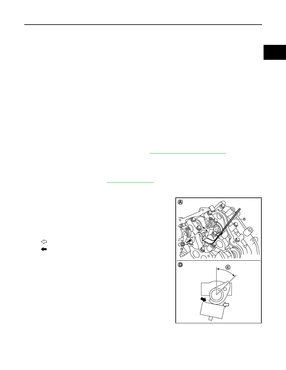
• Before measuring, check that the position of drive shaft nose
is within the angle shown in the figure.
• Refer to the figure for the insertion direction of the feeler
gauge since the direction depends on the bank.
a.
Set No. 1 cylinder at TDC of its compression stroke.
Valve clearance
: Refer to
A
: Bank 2
B
: Feeler gauge (commercial service tool)
c
: 45 degrees (drive shaft nose angle)
D
: View D
: Insertion direction of feeler gauge on the bank 2
: Insertion direction of feeler gauge on the bank 1
JPBIA2297ZZ
EM-170
< PERIODIC MAINTENANCE >
[VK50VE]
CAMSHAFT VALVE CLEARANCE
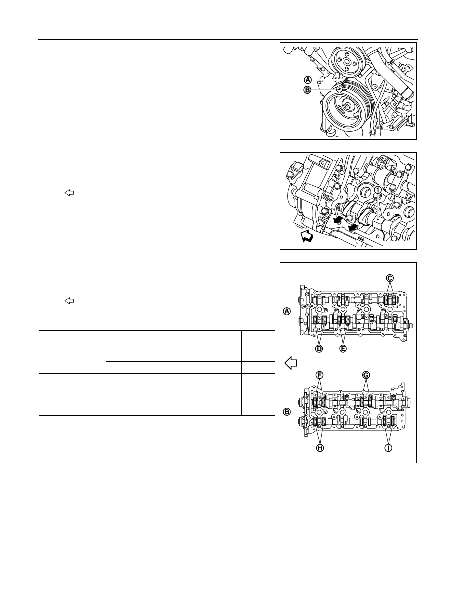
• Rotate crankshaft pulley clockwise to align timing mark
(grooved line without color) (B) with timing indicator (A).
• Check that exhaust cam nose on No. 1 cylinder (engine front
side of bank 1) is located as shown in the figure.
• If not, turn crankshaft one revolution (360 degrees) and align
as shown in the figure.
• By referring to the figure, measure the valve clearances at
locations marked “
×
” as shown in the table below (locations
indicated in the figure).
• No. 1 cylinder at compression TDC
NOTE:
JPBIA2070ZZ
1
: Camshaft (EXH) (bank 1)
: Engine front
JPBIA2071ZZ
: Engine front
Measuring position [bank 2 (A)]
No. 2
CYL.
No. 4
CYL.
No. 6
CYL.
No. 8
CYL.
No. 1 cylinder at com-
pression TDC
EXH
×
(C)
INT
×
(D)
×
(E)
Measuring position [bank 1 (B)]
No. 1
CYL.
No. 3
CYL.
No. 5
CYL.
No. 7
CYL.
No. 1 cylinder at com-
pression TDC
INT
×
(F)
×
(G)
EXH
×
(H)
×
(I)
JPBIA2067ZZ
CAMSHAFT VALVE CLEARANCE
EM-171
< PERIODIC MAINTENANCE >
[VK50VE]
C
D
E
F
G
H
I
J
K
L
M
A
EM
N
P
O
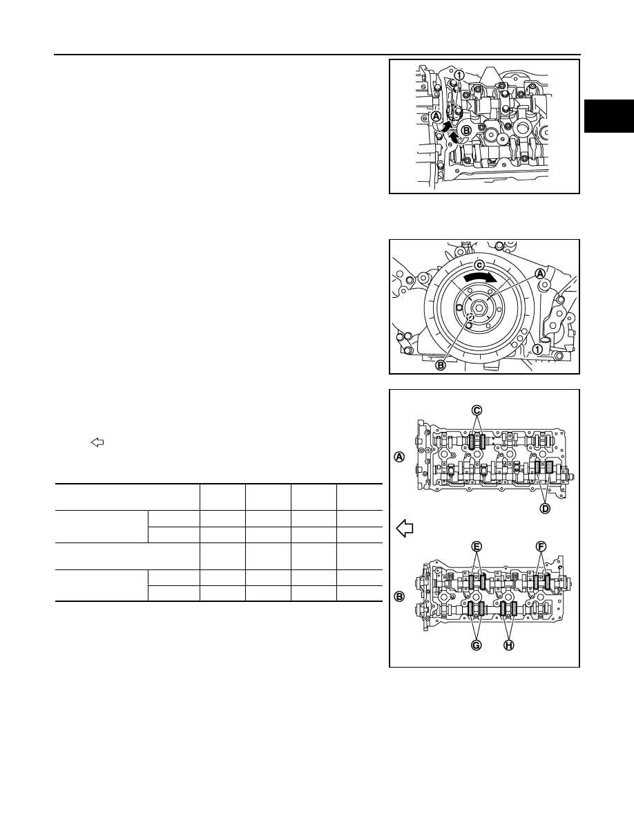
To measure valve clearance of No. 1 cylinder INT valve (front
side), insert feeler gauge (commercial service tool) from the
front side (A) of the control shaft bracket or camshaft (EXH) side
(B).
b.
Rotate crankshaft 270 degrees clockwise (when viewed from engine front) to align No. 3 cylinder at TDC
its compression stroke.
NOTE:
Crankshaft pulley mounting bolt flange has an angle mark (B)
every 90 degrees (c). They can be used as a guide to rotation
angle.
• By referring to the figure, measure the valve clearances at
locations marked “
×
” as shown in the table below (locations
indicated in the figure).
• No. 3 cylinder at compression TDC
c.
Rotate crankshaft 90 degrees clockwise (when viewed from engine front) to align No. 6 cylinder at TDC of
compression stroke.
NOTE:
1
: Valve lifter
JPBIA2326ZZ
A
: Paint mark
JPBIA2066ZZ
: Engine front
Measuring position [bank 2 (A)]
No. 2
CYL.
No. 4
CYL.
No. 6
CYL.
No. 8
CYL.
No. 3 cylinder at com-
pression TDC
EXH
×
(C)
INT
×
(D)
Measuring position [bank 1 (B)]
No. 1
CYL.
No. 3
CYL.
No. 5
CYL.
No. 7
CYL.
No. 3 cylinder at com-
pression TDC
INT
×
(E)
×
(F)
EXH
×
(G)
×
(H)
JPBIA2068ZZ
Нет комментариевНе стесняйтесь поделиться с нами вашим ценным мнением.
Текст