Infiniti FX35, FX50 (S51). Manual — part 1150
HEATER & COOLING UNIT ASSEMBLY
HA-113
< REMOVAL AND INSTALLATION >
[VK50VE]
C
D
E
F
G
H
J
K
L
M
A
B
HA
N
O
P
CAUTION:
• Replace O-rings with new ones. Then apply compressor oil to them when installing.
• Female-side piping connection is thin and easy to deform. Slowly insert the male-side piping
straight in axial direction.
• Insert piping securely until a click is heard.
• After piping connection is completed, pull male-side piping by hand to make sure that connection
does not come loose.
• O-rings differ from low-pressure flexible hose (high-pressure pipe 1) and low-pressure pipe 1 (high-
pressure pipe 2).
• Mark the mounting position of intake sensor bracket prior to removal so that the reinstalled sensor
can be located in the same position.
• Check for leakages when recharging refrigerant.
EXPANSION VALVE
EXPANSION VALVE : Removal and Installation
INFOID:0000000005249979
REMOVAL
1.
Remove low-pressure pipe 1 and high-pressure pipe 2. Refer to
2.
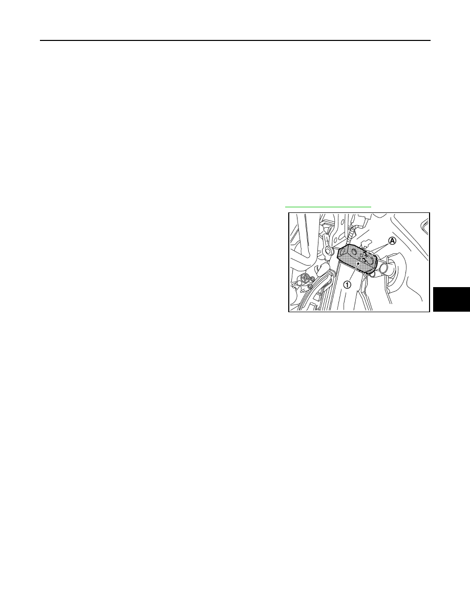
Remove mounting bolts (A), and then remove expansion valve
(1).
CAUTION:
Cap or wrap the joint of evaporator and expansion valve
with suitable material such as vinyl tape to avoid the entry
of air.
INSTALLATION
Installation is basically the reverse order of removal.
CAUTION:
• Replace O-rings with new ones. Then apply compressor oil to them when installing.
• O-rings are different from low-pressure pipe 1 (high-pressure pipe 1) and low-pressure pipe 2 (high-
pressure pipe 2).
• Check for leakages when recharging refrigerant.
JPIIA0710ZZ
HA-114
< REMOVAL AND INSTALLATION >
[VK50VE]
BLOWER UNIT
BLOWER UNIT
Exploded View
INFOID:0000000005249980
BLOWER UNIT
BLOWER UNIT : Removal and Installation
INFOID:0000000005249981
REMOVAL
1.
Remove instrument lower panel RH. Refer to
.
2.
Disconnect AWD control unit connector (AWD). Refer to
3.
Disconnect ECM (1) connectors.
4.
Remove mounting nuts (A), and then remove ECM with bracket
attached.
5.
Remove power steering control unit. Refer to
STC-27, "Removal and Installation"
6.
Disconnect intake door motor connector and blower motor connector.
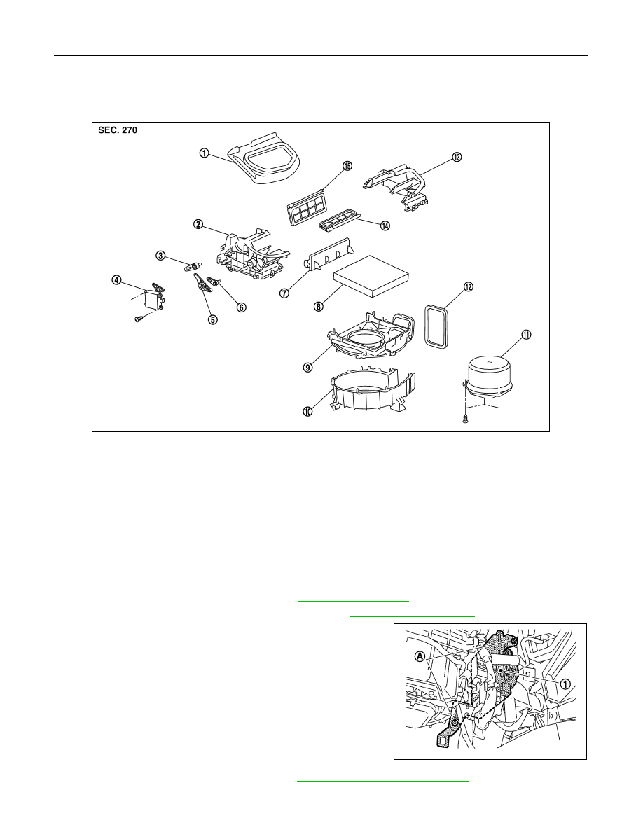
1.
Adapter
2.
Intake box (right)
3.
Intake door lever 2
4.
Intake door motor
5.
Intake door link
6.
Intake door lever 1
7.
Filter cover
8.
In-cabin microfilter
9.
Intake upper case
10. Intake lower case
11.
Blower motor assembly
12. Seal
13. Intake box (left)
14.
Intake door 1
15. Intake door 2
JSIIA0009ZZ
JSIIA1302ZZ
BLOWER UNIT
HA-115
< REMOVAL AND INSTALLATION >
[VK50VE]
C
D
E
F
G
H
J
K
L
M
A
B
HA
N
O
P
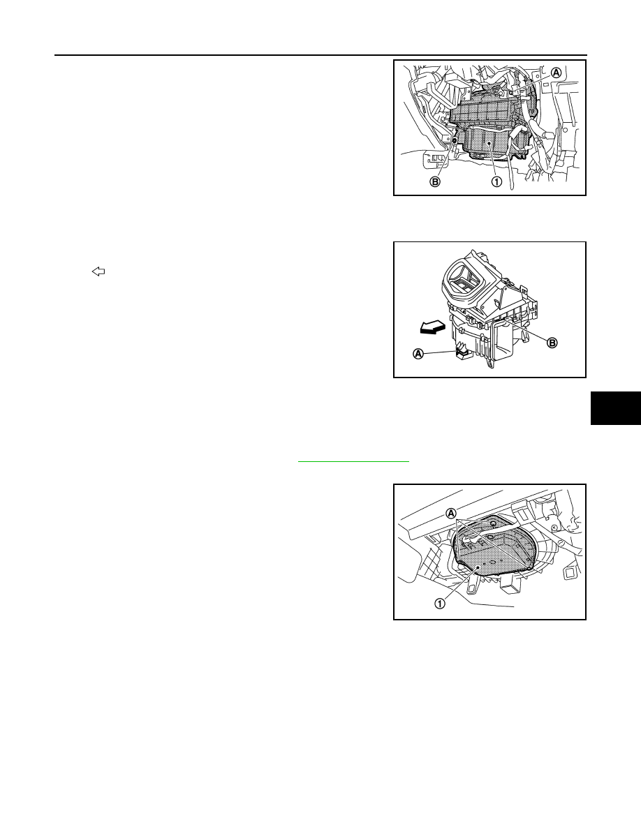
7.
Remove mounting bolt (A) and screw (B), from blower unit (1).
8.
Remove blower unit.
CAUTION:
Move blower unit rightward, and remove locating pin (1
part) and joint. Then remove blower unit downward.
INSTALLATION
Installation is basically the reverse order of removal.
CAUTION:
Make sure locating pin (A) and joint (B) are securely inserted.
BLOWER MOTOR
BLOWER MOTOR : Removal and Installation
INFOID:0000000005249982
REMOVAL
1.
Remove instrument lower cover RH. Refer to
.
2.
Disconnect blower motor connector.
3.
Remove mounting screws (A), and then remove blower motor
(1).
INSTALLATION
Installation is basically the reverse order of removal.
JSIIA1303ZZ
:
Vehicle front
JSIIA0008ZZ
JSIIA1304ZZ

HA-116
< SERVICE DATA AND SPECIFICATIONS (SDS)
[VK50VE]
SERVICE DATA AND SPECIFICATIONS (SDS)
SERVICE DATA AND SPECIFICATIONS (SDS)
SERVICE DATA AND SPECIFICATIONS (SDS)
Compressor
INFOID:0000000005249983
Lubricant
INFOID:0000000005249984
Refrigerant
INFOID:0000000005249985
Engine Idling Speed
INFOID:0000000005249986
Belt Tension
INFOID:0000000005249987
Model
VALEO THERMAL SYSTEMS JAPAN make
DCS-17EC
Type
Variable displacement swash plate
Displacement
cm
3
(cu in)/rev
Max.
171 (10.4)
Number of cylinders
7
Cylinder bore
×
stroke (Max.)
mm (in.)
32 (1.26)
×
30.5 (1.20)
Direction of rotation
Clockwise (viewed from clutch)
Drive belt
Poly V
Disc to pulley clearance
mm (in.)
Standard
0.3 – 0.6 (0.012 – 0.024)
Name
NISSAN A/C System Oil Type S (DH-PS)
Capacity
m
(US fl oz, lmp fl oz)
Total in system
150 (5.07, 5.3)
Compressor (service part) charging
amount
150 (5.07, 5.3)
Type
HFC-134a (R-134a)
Capacity
kg (lb)
0.55 (1.21)
Нет комментариевНе стесняйтесь поделиться с нами вашим ценным мнением.
Текст