Infiniti FX35, FX50 (S51). Manual — part 1148

CONDENSER
HA-105
< REMOVAL AND INSTALLATION >
[VK50VE]
C
D
E
F
G
H
J
K
L
M
A
B
HA
N
O
P
6.
Disconnect refrigerant pressure sensor connector (A) and harness clips (B).
7.
Pull condenser (1) upward of vehicle, and then remove con-
denser (as shown in the figure).
CAUTION:
Be careful not to damage core surface of condenser.
INSTALLATION
Installation is basically the reverse order of removal.
CAUTION:
• Replace O-rings with new ones. Then apply compressor oil to them when installing.
• Female-side piping connection is thin and easy to deform. Slowly insert the male-side piping
straight in axial direction.
• Insert piping securely until a click is heard.
• After piping connection is completed, pull male-side piping by hand to make sure that connection
does not come loose.
• Check for leakages when recharging refrigerant.
CONDENSER PIPE ASSEMBLY
CONDENSER PIPE ASSEMBLY : Removal and Installation
INFOID:0000000005249972
REMOVAL
1.
Use a refrigerant collecting equipment (for HFC-134a) to discharge the refrigerant.
2.
Remove air cleaner case (bank 2). Refer to
3.
Remove air duct (inlet). Refer to
4.
Remove front grille. Refer to
.
5.
Remove mounting bolts (A) from condenser pipe assembly (1).
JSIIA1272ZZ
:
Pawl
JSIIA1273ZZ
JSIIA1274ZZ
HA-106
< REMOVAL AND INSTALLATION >
[VK50VE]
CONDENSER
6.
Disconnect one-touch joint between high-pressure flexible hose
(1) and condenser pipe assembly (3) with disconnector (A)
(SST: 9253089912).
CAUTION:
Cap or wrap the joint of the A/C piping with suitable mate-
rial such as vinyl tape to avoid the entry of air.
7.
Disconnect one-touch joint between high-pressure pipe 1 (2)
and condenser pipe assembly with disconnector (A) (SST:
9253089908).
CAUTION:
Cap or wrap the joint of the A/C piping with suitable mate-
rial such as vinyl tape to avoid the entry of air.
8.
Remove condenser pipe assembly.
CAUTION:
Cap or wrap the joint of the A/C piping and condenser with suitable material such as vinyl tape to
avoid the entry of air.
INSTALLATION
Installation is basically the reverse order of removal.
CAUTION:
• Replace O-rings with new ones. Then apply compressor oil to them when installing.
• Female-side piping connection is thin and easy to deform. Slowly insert the male-side piping
straight in axial direction.
• Insert piping securely until a click is heard.
• After piping connection is completed, pull male-side piping by hand to make sure that connection
does not come loose.
• Check for leakages when recharging refrigerant.
LIQUID TANK
LIQUID TANK : Removal and Installation
INFOID:0000000005249973
REMOVAL
1.
Use a refrigerant collecting equipment (for HFC-134a) to discharge the refrigerant.
2.
Remove air duct (inlet). Refer to
.
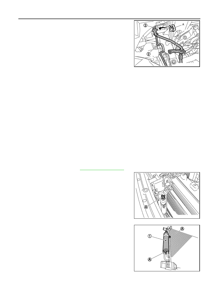
3.
Disconnect refrigerant pressure sensor connector (A).
4.
Clean liquid tank and its surrounding area, and then remove
dust and rust from liquid tank.
CAUTION:
Be sure to clean carefully.
5.
Remove mounting bolts (A) from liquid tank (1).
6.
Remove liquid tank.
CAUTION:
Cap or wrap the joint of the A/C piping and liquid tank with
suitable material such as vinyl tape to avoid the entry of air.
JSIIA1275ZZ
JSIIA1276ZZ
JPIIA0709ZZ
CONDENSER
HA-107
< REMOVAL AND INSTALLATION >
[VK50VE]
C
D
E
F
G
H
J
K
L
M
A
B
HA
N
O
P
INSTALLATION
Install liquid tank, and then install liquid tank bracket on condenser.
CAUTION:
• Check that liquid tank bracket is securely installed at protrusion of condenser. (Check that liquid
tank bracket does not move to a position below center of liquid tank.)
• Replace O-rings of the A/C piping with new ones. Then apply compressor oil to them when installing.
• Check for leakages when recharging refrigerant.
REFRIGERANT PRESSURE SENSOR
REFRIGERANT PRESSURE SENSOR : Removal and Installation
INFOID:0000000005249974
REMOVAL
1.
Remove liquid tank. Refer to
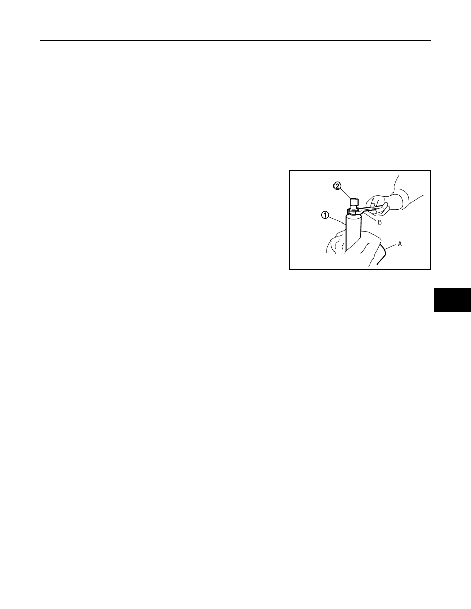
2.
Fix the liquid tank (1) with a vise (A). Remove the refrigerant
pressure sensor (2) with a wrench (B).
CAUTION:
Be careful not to damage liquid tank.
INSTALLATION
Installation is basically the reverse order of removal.
CAUTION:
• Replace O-ring with new one. Then apply compressor oil to them when installing.
• Check for leakages when recharging refrigerant.
JSIIA0075ZZ
HA-108
< REMOVAL AND INSTALLATION >
[VK50VE]
HEATER & COOLING UNIT ASSEMBLY
HEATER & COOLING UNIT ASSEMBLY
Exploded View
INFOID:0000000005249975
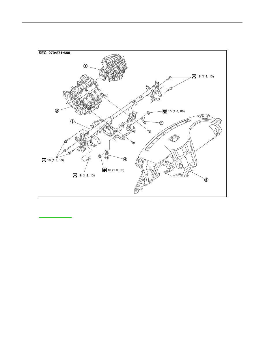
DISASSEMBLY
1.
Blower unit
2.
Heater & cooling unit assembly
3.
Steering member
4.
Instrument stay (left)
5.
Instrument panel assembly
6.
Instrument stay (right)
for symbols in the figure.
JSIIA1305GB
Нет комментариевНе стесняйтесь поделиться с нами вашим ценным мнением.
Текст