Infiniti FX35, FX50 (S51). Manual — part 1149
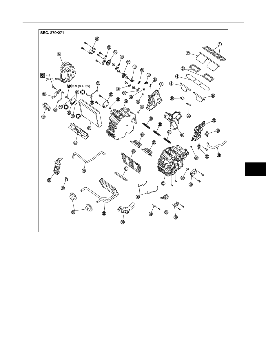
HEATER & COOLING UNIT ASSEMBLY
HA-109
< REMOVAL AND INSTALLATION >
[VK50VE]
C
D
E
F
G
H
J
K
L
M
A
B
HA
N
O
P
1.
Ventilator seal
2.
Ventilator door
3.
Defroster seal
4.
Packing
5.
Defroster door (right)
6.
Packing
7.
Foot duct (right)
8.
Ventilator door spring
9.
Ventilator door lever
10.
Foot door lever
11.
Foot door link
12. Main link sub
13.
Ventilator door link
14.
Main link
15. Mode door motor bracket
16.
Mode door motor
17.
Evaporator cover
18. Low-pressure pipe 1
19.
Cooler pipe grommet
20.
High-pressure pipe 2
21. O-ring
22.
Expansion valve
23.
Evaporator
24. Insulator
25.
Drain hose
26.
Evaporator cover adapter
27. Heater pipe bracket
28.
Heater pipe grommet
29.
Heater core
30. Heater pipe cover
31.
Packing
32.
Case packing
33. Heater & cooling unit case (left)
34.
Ionizer harness bracket
35.
Ionizer
36. Ionizer bracket
37.
Air mix door adapter
38.
Air mix door motor (driver side)
39. J-nut
40.
Front heater duct
41.
Aspirator hose
42. Aspirator
43.
Foot duct (left)
44.
Defroster door (left)
45. Packing
46.
Center case
47.
Foot door (left)
48. Rear ventilator door
JSIIA1602GB

HA-110
< REMOVAL AND INSTALLATION >
[VK50VE]
HEATER & COOLING UNIT ASSEMBLY
HEATER & COOLING UNIT ASSEMBLY
HEATER & COOLING UNIT ASSEMBLY : Removal and Installation
INFOID:0000000005249976
REMOVAL
1.
Set the temperature at 18.0
°
C (60
°
F).
2.
Disconnect the battery cable from the negative terminal.
3.
Use a refrigerant collecting equipment (for HFC-134a) to discharge the refrigerant.
4.
Drain engine coolant from cooling system. Refer to
5.
Remove cowl top cover. Refer to
.
6.
Remove engine cover. Refer to
.
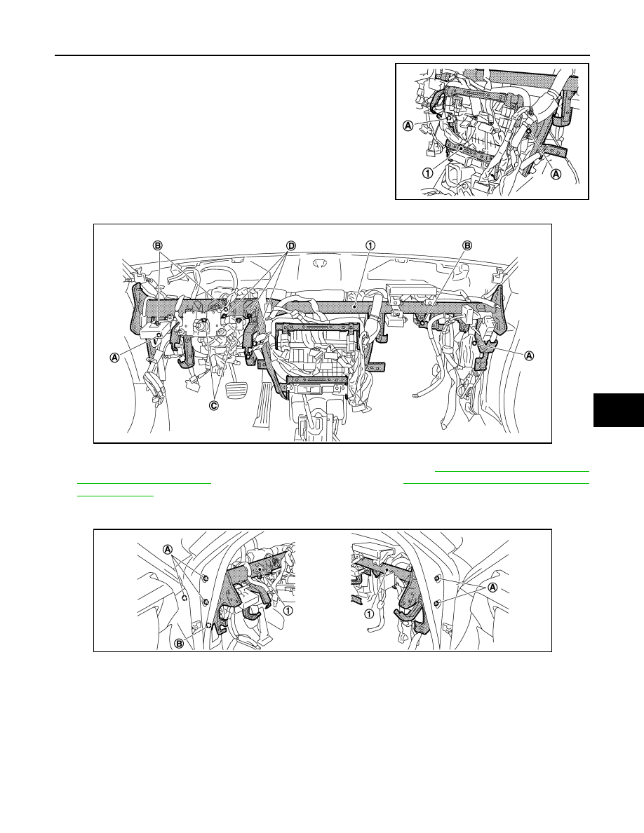
7.
Disconnect one-touch joint between low-pressure pipe 1 (1) and
low-pressure pipe 2 (2) with disconnector (SST: 9253089916)
(A).
CAUTION:
Cap or wrap the joint of the A/C piping with suitable mate-
rial such as vinyl tape to avoid the entry of air.
8.
Disconnect one-touch joint between high-pressure pipe 1 (4)
and high-pressure pipe 2 (3) with disconnector (SST:
9253089908).
CAUTION:
Cap or wrap the joint of the A/C piping with suitable mate-
rial such as vinyl tape to avoid the entry of air.
9.
Remove clamps (A), and then disconnect heater hoses (1).
10. Remove instrument panel assembly. Refer to
11. Remove defroster nozzle and adaptor duct. Refer to
.
12. Remove blower unit. Refer to
.
13. Remove mounting nuts (A), and then remove instrument stay (left) (1) and instrument stay (right) (2).
14. Disconnect drain hose from heater & cooling unit assembly.
49.
Foot door (right)
50.
J-nut
51. Max. cool door lever
52.
Defroster door lever
53.
Defroster door link
54. Max. cool door link
55.
Intake sensor
56.
Intake sensor bracket
57. Air mix door motor (passenger side)
58.
Air mix door adapter
59.
Heater & cooling unit case (right)
60. Max. cool door (right)
61.
Max. cool door (left)
62.
Air mix door (Slide door)
Refer to
for symbols in the figure.
JSIIA1269ZZ
JSIIA1310ZZ
JPIIA0659ZZ
HEATER & COOLING UNIT ASSEMBLY
HA-111
< REMOVAL AND INSTALLATION >
[VK50VE]
C
D
E
F
G
H
J
K
L
M
A
B
HA
N
O
P
15. Remove mounting bolts (A) from steering member (1).
16. Remove mounting bolts (A) from steering member (1).
17. Remove ground bolts (B) from steering member.
18. Remove steering column mounting nuts (C) and bolts (D). Refer to
(WITHOUT ELECTRIC MOTOR) or
(WITH ELECTRIC MOTOR).
19. Remove harness connector and clips of vehicle harness from steering member.
20. Remove mounting bolts (A) from steering member (1).
21. Remove steering member mounting bolt (B).
22. Remove steering member, and then remove heater & cooling unit assembly.
INSTALLATION
Installation is basically the reverse order of removal.
CAUTION:
• Replace O-rings with new ones. Then apply compressor oil to them when installing.
• Female-side piping connection is thin and easy to deform. Slowly insert the male-side piping
straight in axial direction.
• Insert piping securely until a clicks is heard.
• After piping connection is completed, pull male-side piping by hand to make sure that connection
does not come loose.
JSIIA1307ZZ
JSIIA1308ZZ
JSIIA1309ZZ
HA-112
< REMOVAL AND INSTALLATION >
[VK50VE]
HEATER & COOLING UNIT ASSEMBLY
• Check for leakages when recharging refrigerant.
NOTE:
• Refer to
when filling radiator with engine coolant.
• Recharge the refrigerant.
HEATER CORE
HEATER CORE : Removal and Installation
INFOID:0000000005249977
REMOVAL
1.
Remove heater & cooling unit assembly. Refer to
.
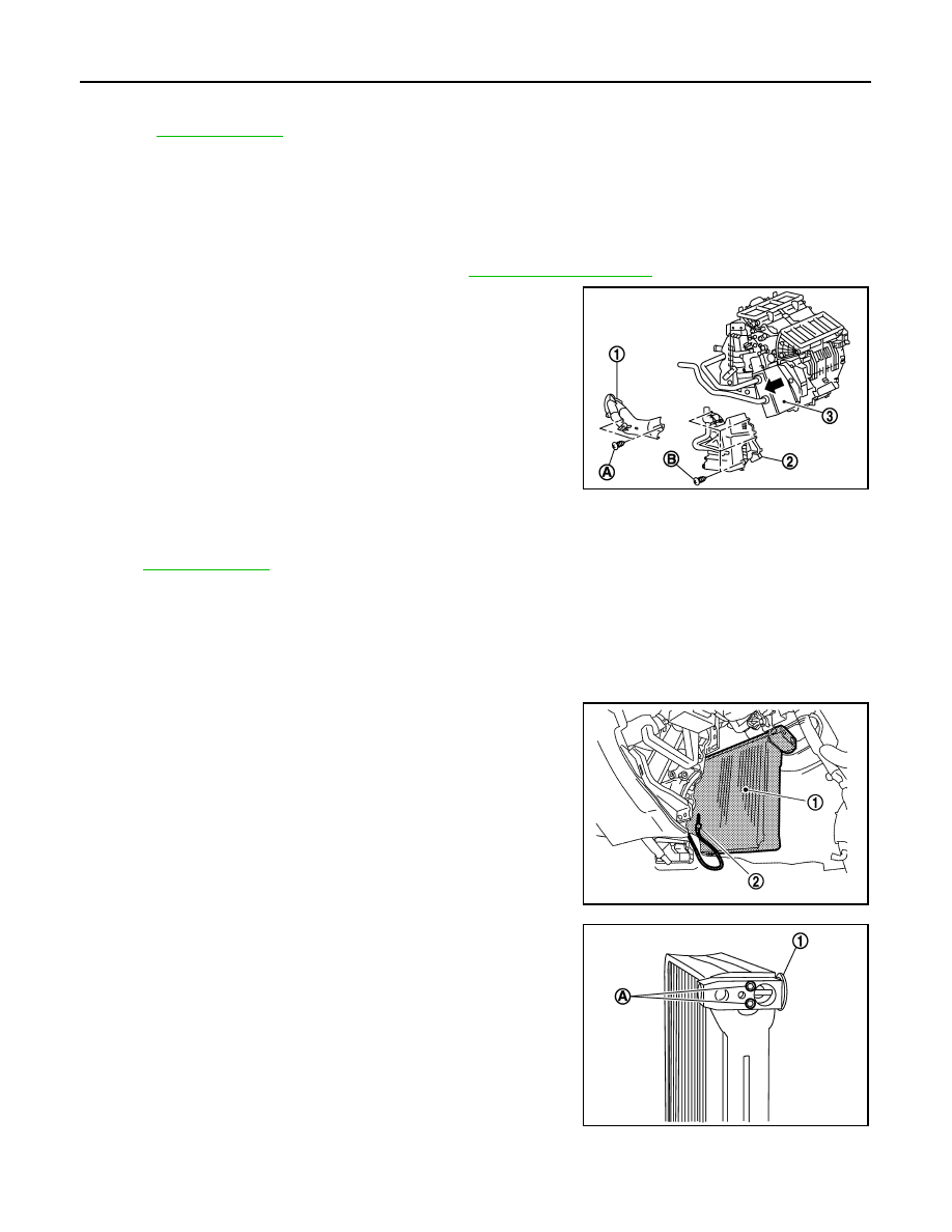
2.
Remove mounting screws (A), and then remove heater pipe
cover (1).
3.
Remove mounting screws (B), and then remove foot duct (left)
(2).
4.
Slide heater core (3) to leftward (as shown in the figure).
INSTALLATION
Installation is basically the reverse order of removal.
NOTE:
Refer to
when filling radiator with engine coolant.
EVAPORATOR
EVAPORATOR : Removal and Installation
INFOID:0000000005249978
REMOVAL
1.
Remove low-pressure pipe 1 and high-pressure pipe 2.
2.
Slide evaporator (1) from heater & cooling unit assembly.
3.
Remove intake sensor (2) from evaporator, and then remove
evaporator.
4.
Remove mounting bolts (A), and then remove expansion valve
(1).
CAUTION:
Cap or wrap the joint of evaporator and expansion valve
with suitable material such as vinyl tape to avoid the entry
of air.
INSTALLATION
Installation is basically the reverse order of removal.
JSIIA0017GB
JSIIA1277ZZ
JSIIA0102ZZ
Нет комментариевНе стесняйтесь поделиться с нами вашим ценным мнением.
Текст