Infiniti FX35, FX50 (S51). Manual — part 1378
MWI
METER SYSTEM
MWI-31
< SYSTEM DESCRIPTION >
C
D
E
F
G
H
I
J
K
L
M
B
A
O
P
ator and electric unit (control unit) through the use of the CAN communication. After the end of cranking and
recognition of engine revolution, the unified meter and A/C amp. transmits a meter effect signal to the combi-
nation meter through the communication line.
• Receiving a meter effect signal, the combination meter illuminates the meter light in stages and sweeps the
needles of the speedometer and the tachometer.
NOTE:
The engine-start effect function enables ON/OFF with an operation of information display.
Cancel Conditions
• Meter effect is not performed during driving.
• Meter effect is not performed except when in P-range.
NOTE:
Meter effect is cancelled when the vehicle is moved during meter effect or the shift lever is shifted to the range
except for P-range.
Ignition Switch OFF Effect Function
The unified meter and A/C amp. transmits a meter effect signal to the combination meter through the commu-
nication line when ignition switch is turned from ON to OFF. Receiving a meter effect signal, the combination
meter turns off the meter illumination in stages. Illumination for the needle is turned off after the meter illumina-
tion is turned off.
MWI-32
< SYSTEM DESCRIPTION >
METER SYSTEM
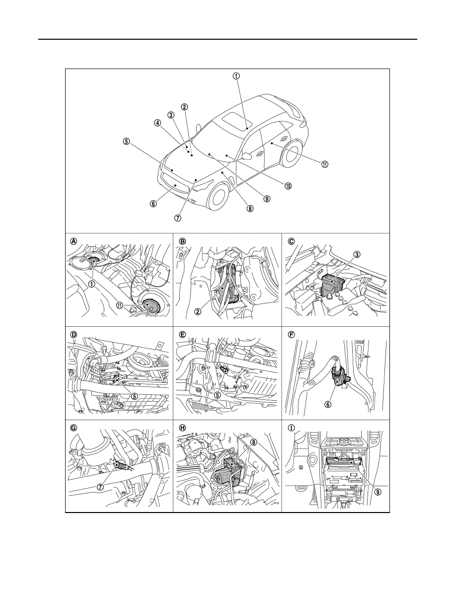
METER EFFECT FUNCTION : Component Parts Location
INFOID:0000000005524587
JPNIA1104ZZ
MWI
METER SYSTEM
MWI-33
< SYSTEM DESCRIPTION >
C
D
E
F
G
H
I
J
K
L
M
B
A
O
P
METER EFFECT FUNCTION : Component Description
INFOID:0000000005524588
INFORMATION DISPLAY
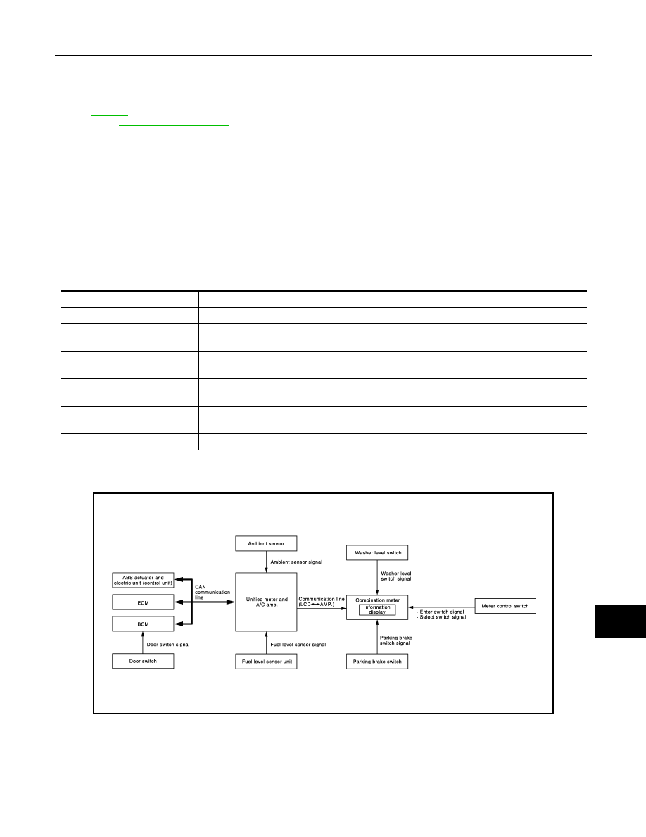
INFORMATION DISPLAY : System Diagram
INFOID:0000000005524589
INFORMATION DISPLAY : System Description
INFOID:0000000005524590
DESCRIPTION
• The combination meter retrieves the information required for controlling the operations of the information
display from the communication signals from the unified meter and A/C amp., etc.
1.
Fuel level sensor unit and fuel pump
(main)
2.
BCM
3.
IPDM E/R
4.
ECM :
(VQ35HR engine models)
ECM :
(VK50VE engine models)
5.
Oil pressure switch (VQ35HR engine
models)
6.
Ambient sensor
7.
Oil pressure switch (VK50VE engine
models)
8.
ABS actuator and electric unit (con-
trol unit)
9.
Unified meter and A/C amp.
10. Combination meter
11.
Fuel level sensor unit (sub)
A.
Rear seat (bottom)
B.
Dash side finisher (passenger side)
C.
Hoodledge cover (RH)
D.
2WD [oil pan (upper) RH side]
E.
AWD [oil filter bracket part (VQ35HR
engine models)]
F.
Condenser (front)
G.
AWD [oil filter bracket part (VK50VE
engine models)]
H.
Hoodledge cover (LH)
I.
Behind cluster lid C
Unit
Description
Combination meter
Receives a meter effect signal through the unified meter and A/C amp. and performs meter effect.
Unified meter and A/C amp.
Receives signals from each unit with the CAN communication and transmits a meter effect signal
to the combination meter through the communication line.
ECM
Transmits an engine speed signal and an engine status signal to the unified meter and A/C amp.
with the CAN communication.
BCM
Transmits a starter relay status signal to the unified meter and A/C amp. with the CAN communi-
cation.
ABS actuator and electric unit
(control unit)
Transmits a vehicle speed signal to the unified meter and A/C amp. with the CAN communication.
TCM
Transmits a shift position signal to the unified meter and A/C amp. with the CAN communication.
JPNIA1096GB

MWI-34
< SYSTEM DESCRIPTION >
METER SYSTEM
• The combination meter incorporates a trip computer that displays the warning / information according to the
information received from various units.
PARKING BRAKE RELEASE WARNING
The combination meter indicates parking brake release warning judged with the vehicle speed signal received
from the unified meter and A/C amp. by means of communication line and the parking brake switch signal from
the parking brake switch.
Warning Operation Condition
Parking brake release warning is judged if all of the following conditions are fulfilled
• Vehicle speed is 7 km/h (4.3 MPH) or higher
• Parking brake switch ON
LOW FUEL WARNING
The combination meter indicates low fuel warning judged with the fuel level sensor signal received from the
unified meter and A/C amp.
Warning Operation Condition
• Fuel level: Approx. 14 (3 - 5/7 US gal, 3 - 1/10 Imp gal) or less
LOW WASHER FLUID WARNING
The combination meter indicates low washer fluid warning judged with the signal from the washer level switch.
Warning Operation Condition
• Indicates the warning when it is in washer level switch ON condition for 180 seconds or more. Release the
warning when it is in washer level switch OFF condition for 30 seconds or more.
LOW OUTSIDE TEMPERATURE WARNING
The combination meter indicates low outside temperature warning judged with the ambient sensor signal
received from the unified meter and A/C amp. by means of communication line.
DOOR OPEN WARNING
The combination meter indicates door open warning judged with each door switch signal received from the
unified meter and A/C amp. by means of communication line.
INSTANTANEOUS FUEL CONSUMPTION
• The unified meter and A/C amp. receives the fuel consumption monitor signal from ECM and the vehicle
speed signal from the ABS actuator and electric unit (control unit) with CAN communication line.
• The unified meter and A/C amp. calculates the instantaneous fuel consumption according to the fuel con-
sumption monitor signal and the vehicle speed signal received with CAN communication line, and transmits
it to the combination meter.
AVERAGE FUEL CONSUMPTION
• The unified meter and A/C amp. receives the fuel consumption monitor signal from ECM and the vehicle
speed signal from the ABS actuator and electric unit (control unit) with CAN communication line.
• The unified meter and A/C amp. calculates the average fuel consumption according to the fuel consumption
monitor signal and the vehicle speed signal received with CAN communication line, and transmits it to the
combination meter.
• The average fuel consumption displayed on the information display is uploaded at approximately 30-second
intervals.
NOTE:
When turning ON the ignition switch after triggering a reset or removing/installing the battery, “
−−−−
” is indi-
cated until 30 seconds/500 m (0.31 mile) of driving.
AVERAGE VEHICLE SPEED
JSNIA0033GB
Нет комментариевНе стесняйтесь поделиться с нами вашим ценным мнением.
Текст