Infiniti FX35, FX50 (S51). Manual — part 1377
MWI
METER SYSTEM
MWI-27
< SYSTEM DESCRIPTION >
C
D
E
F
G
H
I
J
K
L
M
B
A
O
P
WARNING LAMPS/INDICATOR LAMPS : Component Description
INFOID:0000000005524580
METER ILLUMINATION CONTROL
METER ILLUMINATION CONTROL : System Diagram
INFOID:0000000005524581
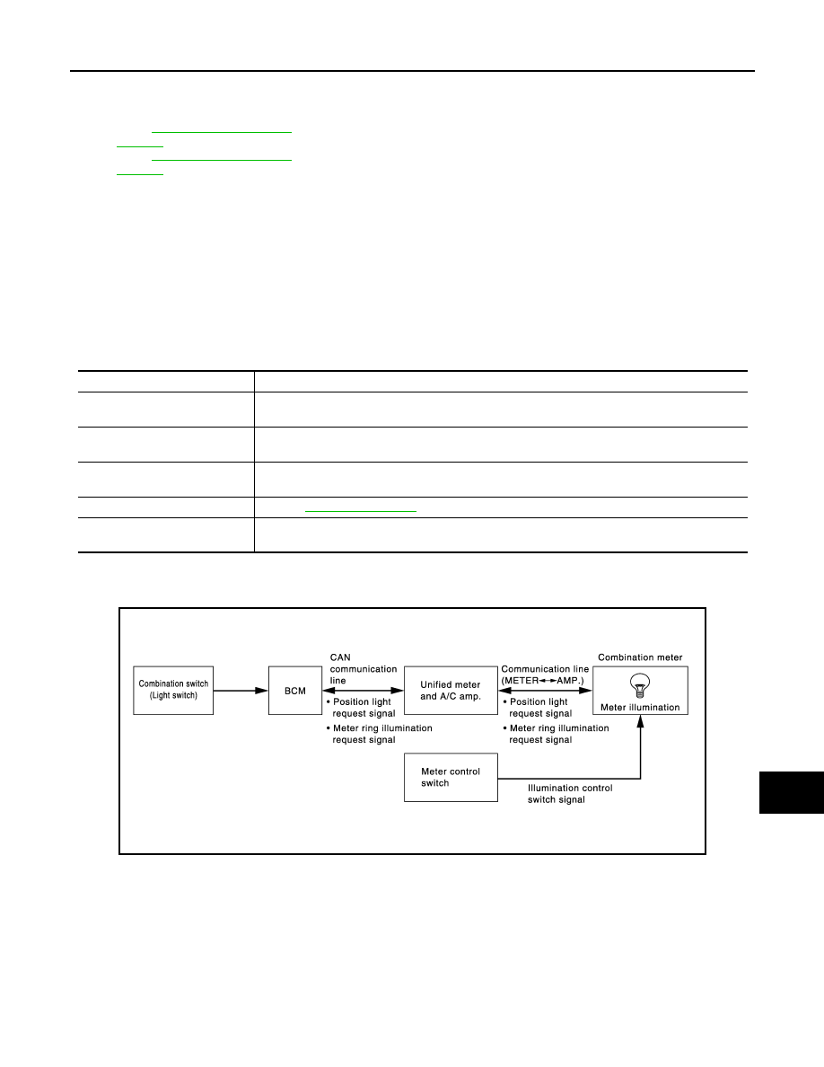
METER ILLUMINATION CONTROL : System Description
INFOID:0000000005524582
SYSTEM DESCRIPTION
The combination meter receives an illumination control switch signal from the meter control switch, and a posi-
tion light request signal and a meter ring illumination request signal from BCM through the unified meter and
A/C amp. to control meter illumination.
Daytime Mode
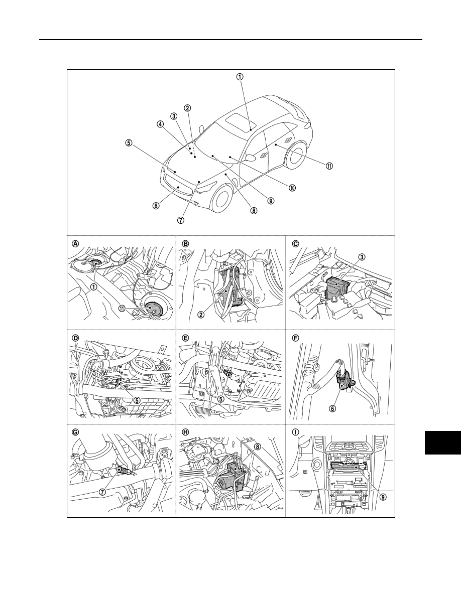
1.
Fuel level sensor unit and fuel pump
(main)
2.
BCM
3.
IPDM E/R
4.
ECM :
(VQ35HR engine models)
ECM :
(VK50VE engine models)
5.
Oil pressure switch (VQ35HR engine
models)
6.
Ambient sensor
7.
Oil pressure switch (VK50VE engine
models)
8.
ABS actuator and electric unit (con-
trol unit)
9.
Unified meter and A/C amp.
10. Combination meter
11.
Fuel level sensor unit (sub)
A.
Rear seat (bottom)
B.
Dash side finisher (passenger side)
C.
Hoodledge cover (RH)
D.
2WD [oil pan (upper) RH side]
E.
AWD [oil filter bracket part (VQ35HR
engine models)]
F.
Condenser (front)
G.
AWD [oil filter bracket part (VK50VE
engine models)]
H.
Hoodledge cover (LH)
I.
Behind cluster lid C
Unit
Description
Combination meter
Turns the oil pressure warning lamp ON/OFF according to the oil pressure switch signal received
from the unified meter and A/C amp. by means of communication line.
Unified meter and A/C amp.
Transmits the oil pressure switch signal received from the IPDM E/R with BCM to the combination
meter by means of communication line.
IPDM E/R
IPDM E/R reads the ON/OFF signals from the oil pressure switch and transmits the oil pressure
switch signal to the unified meter and A/C amp. via BCM with the CAN communication line.
Oil pressure switch
.
BCM
Transmits the oil pressure switch signal received from IPDM E/R via CAN communication to the
unified meter and A/C amp. via CAN communication line.
JPNIA1076GB

MWI-28
< SYSTEM DESCRIPTION >
METER SYSTEM
Meter illumination is adjusted to 5 steps by illumination control switch
(1) in daytime mode.
Nighttime Mode
• Combination meter is transferred to nighttime mode with position light request signal from BCM with CAN
communication line.
• Meter illumination is adjusted to 22 steps by illumination control switch in nighttime.
Driver Welcome Function
• BCM transmits a meter ring illumination request signal to the unified meter and A/C amp. through the CAN
communication when the intelligent key is inside the vehicle and the door on the driver side is recognized as
closed.
• The unified meter and A/C amp. receives a meter ring illumination request signal through the CAN commu-
nication and transmits the signal to the combination meter with communication line.
• The combination meter turns on meter ring illumination is stages by receiving a meter ring illumination
request signal from the unified meter and A/C amp. through the communication line.
NOTE:
Meter ring illumination turns off in stages after a set period of time.
JPNIA1077ZZ
MWI
METER SYSTEM
MWI-29
< SYSTEM DESCRIPTION >
C
D
E
F
G
H
I
J
K
L
M
B
A
O
P
METER ILLUMINATION CONTROL : Component Parts Location
INFOID:0000000005524583
JPNIA1104ZZ
MWI-30
< SYSTEM DESCRIPTION >
METER SYSTEM
METER ILLUMINATION CONTROL : Component Description
INFOID:0000000005524584
METER EFFECT FUNCTION
METER EFFECT FUNCTION : System Diagram
INFOID:0000000005524585
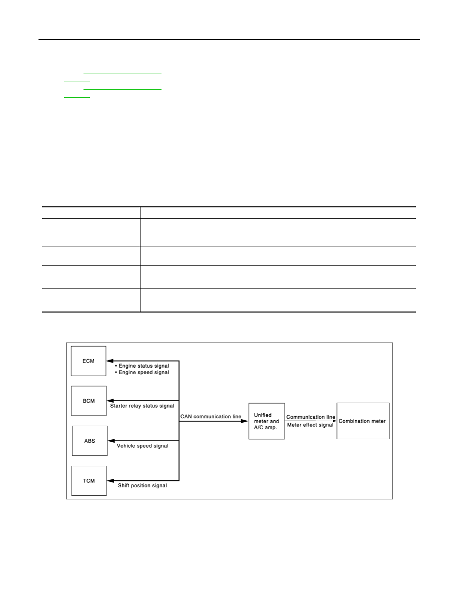
METER EFFECT FUNCTION : System Description
INFOID:0000000005524586
SYSTEM DESCRIPTION
Engine-start Effect function
• The unified meter and A/C amp. receives an engine speed signal and engine status signal from ECM, a
starter relay status signal from BCM, a shift position signal from TCM, a vehicle speed signal from ABS actu-
1.
Fuel level sensor unit and fuel pump
(main)
2.
BCM
3.
IPDM E/R
4.
ECM :
(VQ35HR engine models)
ECM :
(VK50VE engine models)
5.
Oil pressure switch (VQ35HR engine
models)
6.
Ambient sensor
7.
Oil pressure switch (VK50VE engine
models)
8.
ABS actuator and electric unit (con-
trol unit)
9.
Unified meter and A/C amp.
10. Combination meter
11.
Fuel level sensor unit (sub)
A.
Rear seat (bottom)
B.
Dash side finisher (passenger side)
C.
Hoodledge cover (RH)
D.
2WD [oil pan (upper) RH side]
E.
AWD [oil filter bracket part (VQ35HR
engine models)]
F.
Condenser (front)
G.
AWD [oil filter bracket part (VK50VE
engine models)]
H.
Hoodledge cover (LH)
I.
Behind cluster lid C
Unit
Description
Combination meter
Controls the meter illumination with the illumination control switch signal from the meter control
switch and the position light request signal and the meter ring illumination request signal from uni-
fied meter and A/C amp.
Unified meter and A/C amp.
Transmits the position light request signal and meter ring illumination request signal received from
BCM via CAN communication to the combination meter by means of communication.
BCM
Transmits the following signals to the unified meter and A/C amp.
• Position light request signal
• Meter ring illumination request signal
Meter control switch
Transmits the following signals to the combination meter.
• Illumination control switch signal (+)
• Illumination control switch signal (–)
JPNIA1078GB
Нет комментариевНе стесняйтесь поделиться с нами вашим ценным мнением.
Текст