Infiniti FX35, FX50 (S51). Manual — part 1379

MWI
METER SYSTEM
MWI-35
< SYSTEM DESCRIPTION >
C
D
E
F
G
H
I
J
K
L
M
B
A
O
P
• The unified meter and A/C amp. receives the vehicle speed signal from the ABS actuator and electric unit
(control unit) via CAN communication line.
• Measures the time during the ignition switch ON with the unified meter and A/C amp.
• The unified meter and A/C amp. calculates the average vehicle speed according to the above signals. These
signals are transmitted to the combination meter with the communication line.
• The average vehicle speed displayed on the information display is uploaded at approximately 30-second
intervals.
NOTE:
When turning ON the ignition switch after triggering a reset or removing/installing the battery, “
−−−−
” is indi-
cated until 30 seconds/500 m (0.31 mile) of driving.
TRAVEL TIME
Measures the time during the ignition switch ON with the unified meter and A/C amp, and transmits it to the
combination meter by means of communication line.
TRAVEL DISTANCE
• The unified meter and A/C amp. transmits the vehicle speed signal from ABS actuator and electric unit (con-
trol unit) to the combination meter.
• The combination meter calculates the vehicle distance according to the vehicle speed signal. The vehicle
distance is displayed.
POSSIBLE DRIVING DISTANCE
The unified meter and A/C amp. calculates possible driving distance according to the vehicle speed signal and
fuel consumption monitor signal transmitted via CAN communication and the fuel level sensor signal transmit-
ted from the fuel level sensor. These signals are transmitted to the combination meter with the communication
line.
NOTE:
• When turning ON the ignition switch after removing/installing the battery, “
−−−−
” is indicated until 30 sec-
onds.
• The indicated values may not match each other when filling the fuel with the ignition switch ON. Refer to
MWI-143, "INFORMATION DISPLAY : Description"
.
AMBIENT AIR TEMPERATURE
• The unified meter and A/C amp. receives the ambient sensor signal from the ambient sensor.
• The unified meter and A/C amp. calculates the ambient temperature according to the ambient sensor signal,
and transmits it to the combination meter.
• The indicated temperature does not increase if the vehicle speed is less than 20 km/h (12 MPH).
NOTE:
• The ambient sensor input value that is displayed on “Data Monitor” of CONSULT-III is the value before the
correction. It may not match the indicated temperature on the information display.
• Ambient temperature may be indicated higher than an actual temperature, depending on heat in the engine,
a road surface temperature, and so on.
SETTING
Setting item list
Items
Setting range
Setting unit
Description
ALERT
TIME TO REST
No setting - 6 hours
30 minutes,
[60 minutes]*
Time to rest is displayed on the informa-
tion display if the vehicle reached the set
travel distance.
ICY
ON/OFF
—
Low outside temp is displayed on the in-
formation display if the ambient tempera-
ture is 3
°
C (37
°
F) or less.

MWI-36
< SYSTEM DESCRIPTION >
METER SYSTEM
* : Press and hold the switch (1 second or more).
MAINTENANCE
ENGINE OIL
No setting - 18,500 miles,
(No setting - 30,000 km)
250 miles (500 km),
[500 miles (1000 km)]*
The engine oil replacement interval is dis-
played on the information display if the ve-
hicle reached the set distance.
OIL FILTER
No setting - 18,500 miles,
(No setting - 30,000 km)
250 miles (500 km),
[500 miles (1000 km)]*
The oil filter replacement interval is dis-
played on the information display if the ve-
hicle reached the set distance.
TIRE
No setting - 18,500 miles,
(No setting - 30,000 km)
250 miles (500 km),
[500 miles (1000 km)]*
The tire replacement interval is displayed
on the information display if the vehicle
reached the set distance.
OTHER
No setting - 18,500 miles,
(No setting - 30,000 km)
250 miles (500 km),
[500 miles (1000 km)]*
The other replacement interval is dis-
played on the information display if the ve-
hicle reached the set distance.
CUSTOMIZE
LANGUAGE
ENGLISH/FRANCAIS
—
Changing the language setting can be
performed.
UNIT
US/METRIC
—
Changing the unit setting can be per-
formed.
METER EF-
FECT
ON/OFF
—
Changing the meter effect setting can be
performed.
Items
Setting range
Setting unit
Description
MWI
METER SYSTEM
MWI-37
< SYSTEM DESCRIPTION >
C
D
E
F
G
H
I
J
K
L
M
B
A
O
P
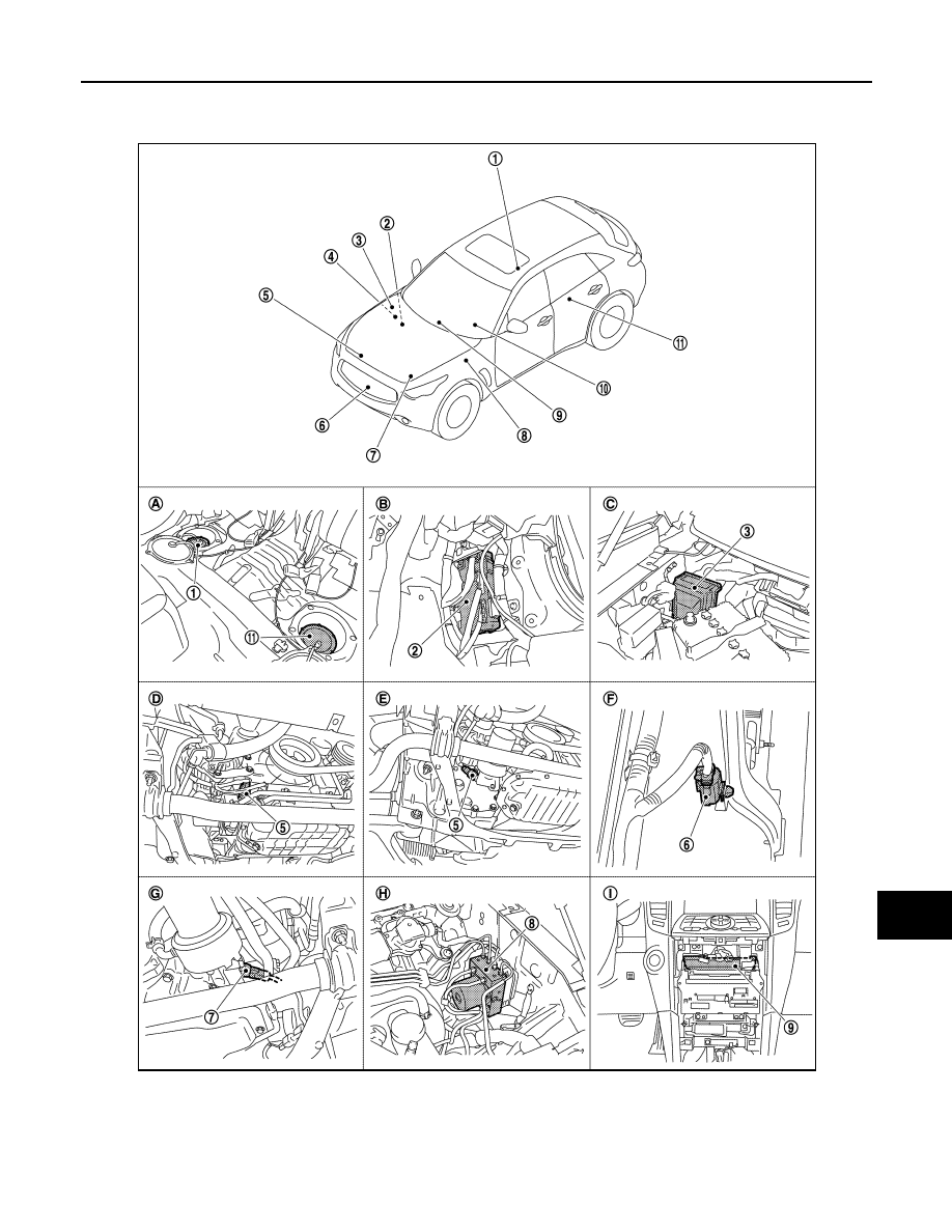
INFORMATION DISPLAY : Component Parts Location
INFOID:0000000005524591
JPNIA1104ZZ

MWI-38
< SYSTEM DESCRIPTION >
METER SYSTEM
INFORMATION DISPLAY : Component Description
INFOID:0000000005524592
1.
Fuel level sensor unit and fuel pump
(main)
2.
BCM
3.
IPDM E/R
4.
ECM :
(VQ35HR engine models)
ECM :
(VK50VE engine models)
5.
Oil pressure switch (VQ35HR engine
models)
6.
Ambient sensor
7.
Oil pressure switch (VK50VE engine
models)
8.
ABS actuator and electric unit (con-
trol unit)
9.
Unified meter and A/C amp.
10. Combination meter
11.
Fuel level sensor unit (sub)
A.
Rear seat (bottom)
B.
Dash side finisher (passenger side)
C.
Hoodledge cover (RH)
D.
2WD [oil pan (upper) RH side]
E.
AWD [oil filter bracket part (VQ35HR
engine models)]
F.
Condenser (front)
G.
AWD [oil filter bracket part (VK50VE
engine models)]
H.
Hoodledge cover (LH)
I.
Behind cluster lid C
Unit
Description
Combination meter
Controls the information display with the signals received from the unified meter and A/C amp. by
means of communication and the signals from various switches and sensors.
Unified meter and A/C amp.
Transmits signals received from various units to the combination meter by means of communica-
tion.
Fuel level sensor unit
Refer to
ECM
Transmits the following signals to the unified meter and A/C amp. via CAN communication.
• Engine speed signal
• Fuel consumption monitor signal
ABS actuator and electric unit
(control unit)
Transmits the vehicle speed signal to the unified meter and A/C amp. via CAN communication.
BCM
Transmits signals provided by various units to the unified meter and A/C amp. via CAN commu-
nication.
Meter control switch
Transmits the following signals to the combination meter.
• Enter switch signal
• Select switch signal
Washer level switch
Transmits the washer level signal to the combination meter.
Parking brake switch
Refer to
Door switch
Transmits the door switch signals to BCM.
Ambient sensor
Detects the ambient air temperature and transmits the ambient sensor signal to the unified meter
and A/C amp.
Нет комментариевНе стесняйтесь поделиться с нами вашим ценным мнением.
Текст