Infiniti FX35, FX50 (S51). Manual — part 1215
INL-60
< DTC/CIRCUIT DIAGNOSIS >
TAIL LAMP SIGNAL CIRCUIT
TAIL LAMP SIGNAL CIRCUIT
Description
INFOID:0000000005245601
Total illumination control unit inputs tail lamp signal from IPDM E/R.
Component Function Check
INFOID:0000000005245602
NOTE:
Check the tail lamp circuit if the tail lamp is not turned ON. Refer to
EXL-88, "Component Function Check"
.
1.
CHECK TAIL LAMP SIGNAL INPUT WITH CONSULT-III
CONSULT-III DATA MONITOR
1.
Turn ignition switch ON.
2.
Select “TAIL LAMP SIGNAL” of TOTAL ILLUM C/U data monitor item.
3.
While operating the lighting switch, check the monitor status.
Is the measurement value normal?
YES
>> Tail lamp signal circuit is normal.
NO
>> Refer to
.
Diagnosis Procedure
INFOID:0000000005245603
1.
CHECK TAIL LAMP INPUT SIGNAL
CONSULT-III ACTIVE TEST
1.
Turn ignition switch ON.
2.
Select “EXTERNAL LAMPS” of IPDM E/R active test item.
3.
While operating the test item, check the voltage between the total illumination control unit and ground.
Is the measurement value normal?
YES
>> Replace the total illumination control unit.
NO
>> GO TO 2.
2.
CHECK TAIL LAMP SIGNAL CIRCUIT FOR OPEN
1.
Turn ignition switch OFF.
2.
Disconnect the IPDM E/R harness connector and total illumination harness connector.
3.
Check continuity between the IPDM E/R harness connector and total illumination harness connector.
Does continuity exist?
Monitor item
Condition
Monitor status
Lighting switch
TAIL LAMP SIGNAL
OFF
Off
1ST
On
Terminals
Test item
Voltage
(Approx.)
(+)
(–)
Total illumination control
unit
Ground
EXTERNAL
LAMPS
Connector
Terminal
M129
4
TAIL
Battery
voltage
Off
0 V
IPDM E/R
Total illumination control unit
Continuity
Connector
Terminal
Connector
Terminal
E5
7
M129
4
Existed
TAIL LAMP SIGNAL CIRCUIT
INL-61
< DTC/CIRCUIT DIAGNOSIS >
C
D
E
F
G
H
I
J
K
M
A
B
INL
N
O
P
YES
>> GO TO 3.
NO
>> Repair the harnesses or connectors.
3.
CHECK TAIL LAMP SIGNAL CIRCUIT FOR SHORT
Check continuity between the total illumination control unit and ground.
Does continuity exist?
YES
>> Repair the harnesses or connectors.
NO
>> Replace the IPDM E/R.
Total illumination control unit
Ground
Continuity
Connector
Terminal
M129
4
Not existed
INL-62
< DTC/CIRCUIT DIAGNOSIS >
ILLUMINATION CONTROL SIGNAL CIRCUIT
ILLUMINATION CONTROL SIGNAL CIRCUIT
Component Function Check
INFOID:0000000005245604
1.
CHECK ILLUMINATION CONTROL SIGNAL INPUT BY CONSULT-III
CONSULT-III DATA MONITOR
1.
Turn ignition switch ON.
2.
Switch the lighting switch 1ST.
3.
Select “ILLUM CONT SIGNAL” of TOTAL ILLUM C/U data monitor item.
4.
While operating the illumination control switch, check the monitor status.
Is the item status normal?
YES
>> Illumination control signal circuit is normal.
NO
>> Refer to
.
Diagnosis Procedure
INFOID:0000000005245605
1.
CHECK ILLUMINATION CONTROL SIGNAL INPUT
1.
Switch the lighting switch 1ST.
2.
While operating the illumination control switch, check the voltage between the total illumination control
unit harness connector and the ground.
Is the measurement value normal?
YES
>> Replace the total illumination control unit.
NO
>> GO TO 2.
2.
CHECK ILLUMINATION CONTROL SIGNAL CIRCUIT FOR OPEN
1.
Turn ignition switch OFF.
2.
Disconnect the total illumination control unit connector and the combination meter connector.
3.
Check continuity between the total illumination control unit harness connector and the combination meter
harness connector.
Monitor item
Condition
Monitor status
ILLUM CONT
SIGNAL
Brightness level
Maximum
100 %
Midway
50 %
Minimum
0 %
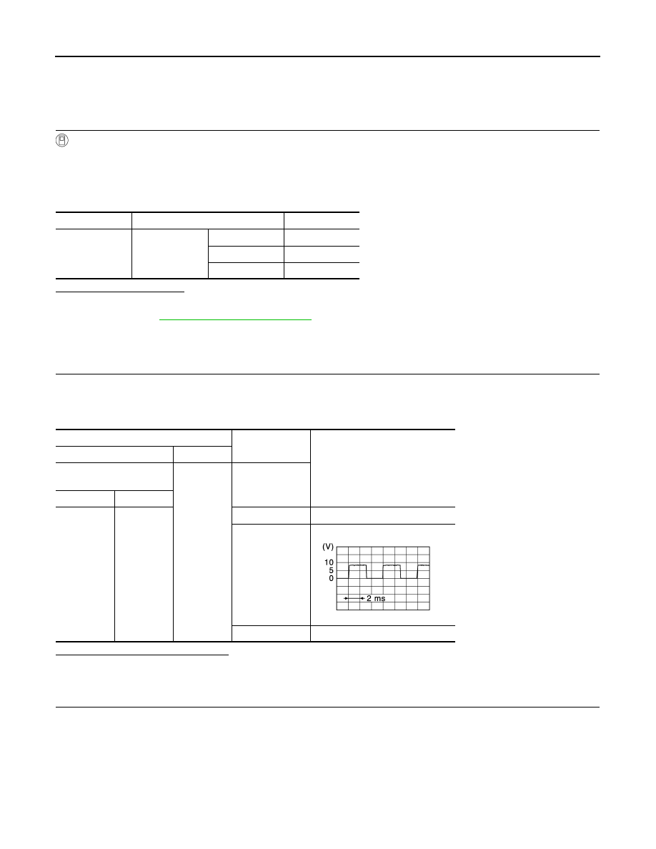
Terminals
Condition
Voltage (Approx.)
(+)
(
−
)
Total illumination control
unit
Ground
Brightness level
Connector
Terminal
M129
24
Maximum
0 V
Midway
Minimum
8 V
JPLIA1199ZZ
ILLUMINATION CONTROL SIGNAL CIRCUIT
INL-63
< DTC/CIRCUIT DIAGNOSIS >
C
D
E
F
G
H
I
J
K
M
A
B
INL
N
O
P
Does continuity exist?
YES
>> GO TO 3.
NO
>> Repair the harnesses or connectors.
3.
CHECK ILLUMINATION CONTROL SIGNAL SHORT CIRCUIT
1.
Disconnect the selector lever position indicator connector.
2.
Check continuity between the total illumination control unit harness connector and the ground.
Does continuity exist?
YES
>> Repair the harnesses or connectors.
NO
>> Replace the total illumination control unit.
Total illumination control unit
Combination meter
Continuity
Connector
Terminal
Connector
Terminal
M129
24
M53
34
Existed
Total illumination control unit
Ground
Continuity
Connector
Terminal
M129
24
Not existed
Нет комментариевНе стесняйтесь поделиться с нами вашим ценным мнением.
Текст