Infiniti FX35, FX50 (S51). Manual — part 1216
INL-64
< DTC/CIRCUIT DIAGNOSIS >
MAP LAMP SWITCH CIRCUIT
MAP LAMP SWITCH CIRCUIT
Component Function Check
INFOID:0000000005245606
1.
CHECK MAP LAMP SWITCH SIGNAL BY CONSULT-III
CONSULT-III DATA MONITOR
1.
Turn ignition switch ON.
2.
Select “MAP LAMP SW” of TOTAL ILLUM C/U data monitor item.
3.
While operating the map lamp main switch, check the monitor status.
Is the item status normal?
YES
>> Map lamp main switch circuit is normal.
NO
>> Refer to
.
Diagnosis Procedure
INFOID:0000000005245607
1.
CHECK MAP LAMP SWITCH SIGNAL INPUT
1.
Turn ignition switch ON.
2.
While operating the map lamp main switch, check the voltage between the total illumination control unit
harness connector and ground.
Is the measurement value normal?
YES
>> Replace the total illumination control unit.
NO
>> GO TO 2.
2.
CHECK MAP LAMP MAIN SWITCH
1.
Turn ignition switch OFF.
2.
Disconnect total illumination control unit connector.
3.
While operating the map lamp main switch, check continuity between the total illumination control unit
harness connector and ground.
Monitor item
Condition
Monitor status
MAP LAMP SW
Map lamp main switch
DOOR
Door
ON
All On
OFF
Off
Terminals
Condition
Voltage
(Approx.)
(+)
(
−
)
Total illumination control unit
Ground
Map lamp main
switch
Connector
Terminal
M129
26
DOOR
0 V
OFF or ALL ON
5 V
27
ALL ON
0 V
OFF or DOOR
5 V
MAP LAMP SWITCH CIRCUIT
INL-65
< DTC/CIRCUIT DIAGNOSIS >
C
D
E
F
G
H
I
J
K
M
A
B
INL
N
O
P
Is the measurement value normal?
YES
>> Replace the total illumination control unit.
NO
>> GO TO 3.
3.
CHECK MAP LAMP SWITCH SIGNAL CIRCUIT FOR OPEN
1.
Turn ignition switch OFF.
2.
Disconnect the map lamp connector.
3.
Check continuity between the total illumination control unit harness connector and map lamp harness con-
nector.
Does continuity exist?
YES
>> GO TO 4.
NO
>> Repair the harnesses or connectors.
4.
CHECK MAP LAMP SWITCH SIGNAL CIRCUIT FOR SHORT
Check continuity between the total illumination control unit harness connector and ground.
Does continuity exist?
YES
>> Repair the harnesses or connectors.
NO
>> GO TO 5.
5.
CHECK MAP LAMP MAIN SWITCH GROUND CIRCUIT FOR OPEN
Check continuity between the map lamp harness connector and ground.
Does continuity exist?
YES
>> Replace the map lamp assembly (map lamp main switch).
NO
>> Repair the harness or connector.
Total illumination control unit
Ground
Condition
Continuity
Connector
Terminal
Map lamp
main switch
M129
26
DOOR
Existed
ALL ON
Not existed
OFF
Not existed
27
DOOR
Not existed
ALL ON
Existed
OFF
Not existed
Total illumination control unit
Map lamp
Continuity
Connector
Terminal
Connector
Terminal
M129
26
R15
1
Existed
27
2
Total illumination control unit
Ground
Continuity
Connector
Terminal
M129
26
Not existed
27
Map lamp
Ground
Continuity
Connector
Terminal
R15
3
Existed
INL-66
< DTC/CIRCUIT DIAGNOSIS >
DOOR SWITCH CIRCUIT
DOOR SWITCH CIRCUIT
Component Function Check
INFOID:0000000005245608
1.
CHECK EACH DOOR SWITCH SIGNAL BY CONSULT-III
CONSULT-III DATA MONITOR
1.
Turn ignition switch ON.
2.
Select “DOOR SW-DR”, “DOOR SW-AS”, “DOOR SW-RR” and “DOOR SW-RL” of TOTAL ILLUM C/U
data monitor item.
3.
While operating each door switch, check the monitor status.
Is the item status normal?
YES
>> Each door switch circuit is normal.
NO
>> Refer to
.
Diagnosis Procedure
INFOID:0000000005245609
1.
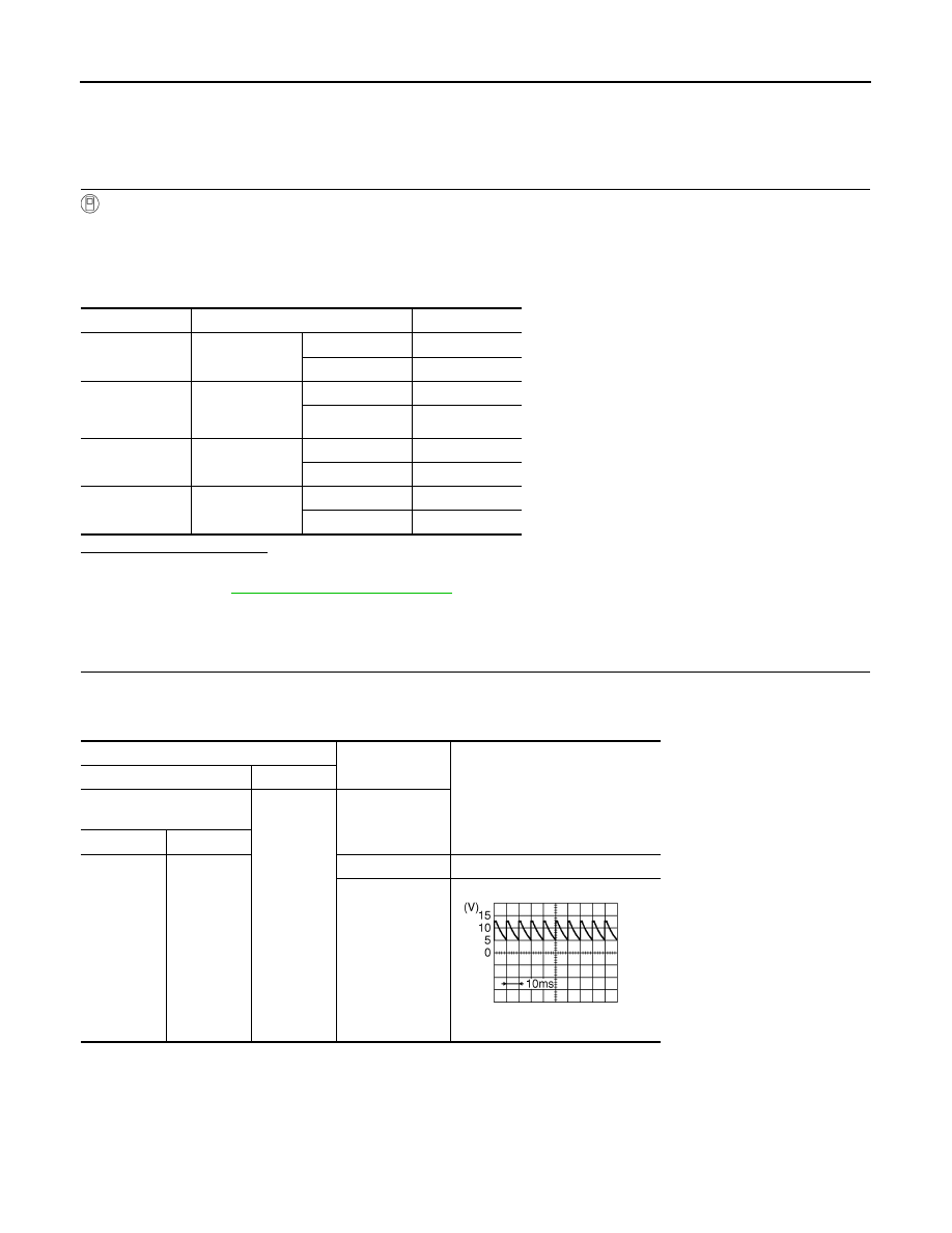
CHECK EACH DOOR SWITCH INPUT SIGNAL
While operating each door switch, check the voltage between the total illumination control unit harness con-
nector and the ground.
Front door (driver side)
Monitor item
Condition
Monitor status
DOOR-SW-DR
Front door
(driver side)
Open
On
Close
Off
DOOR-SW-AS
Front door
(passenger
side)
Open
On
Close
Off
DOOR-SW-RR
Rear door
(RH)
Open
On
Close
Off
DOOR-SW-RL
Rear door
(LH)
Open
On
Close
Off
Terminals
Condition
Voltage (Approx.)
(+)
(
−
)
Total illumination control
unit
Ground
Door
Connector
Terminal
M129
29
Open
0 V
Close
8.5 - 9.0 V
JPMIA0594GB
DOOR SWITCH CIRCUIT
INL-67
< DTC/CIRCUIT DIAGNOSIS >
C
D
E
F
G
H
I
J
K
M
A
B
INL
N
O
P
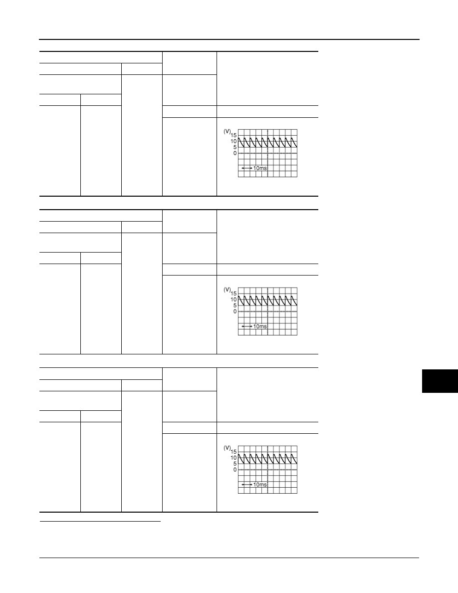
Front door (passenger side)
Rear door (LH)
Rear door (RH)
Is the measurement value normal?
Fixed at 8.5 - 9.5 V>>Replace the total illumination control unit.
Fixed at 0 V>>GO TO 2.
2.
CHECK TOTAL ILLUMINATION CONTROL UNIT (INTERNAL SHORT)
1.
Turn ignition switch OFF.
Terminals
Condition
Voltage (Approx.)
(+)
(
−
)
Total illumination control
unit
Ground
Door
Connector
Terminal
M129
8
Open
0 V
Close
8.5 - 9.0 V
Terminals
Condition
Voltage (Approx.)
(+)
(
−
)
Total illumination control
unit
Ground
Door
Connector
Terminal
M129
9
Open
0 V
Close
8.5 - 9.0 V
Terminals
Condition
Voltage (Approx.)
(+)
(
−
)
Total illumination control
unit
Ground
Door
Connector
Terminal
M129
25
Open
0 V
Close
8.5 - 9.0 V
JPMIA0594GB
JPMIA0594GB
JPMIA0594GB
Нет комментариевНе стесняйтесь поделиться с нами вашим ценным мнением.
Текст