Infiniti FX35, FX50 (S51). Manual — part 1214
INL-56
< DTC/CIRCUIT DIAGNOSIS >
HOSPITALITY ILLUMINATION CIRCUIT
3.
CHECK EACH ILLUMINATION POWER SUPPLY
1.
Turn ignition switch OFF.
2.
Disconnect each illumination connectors.
3.
Turn ignition switch ON.
4.
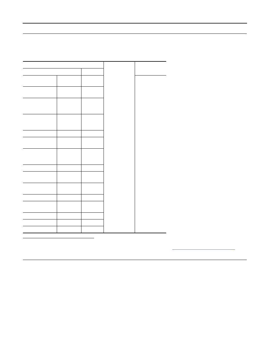
Check voltage between each illumination harness connectors and ground.
Is the measurement value normal?
YES
>> GO TO 4.
NO
>> Check the hospitality lighting power supply circuit 3. Refer to
.
4.
CHECK ILLUMINATION CONTROL CIRCUIT FOR OPEN
1.
Turn ignition switch OFF.
2.
Disconnect the total illumination control unit connector.
3.
Check continuity between the total illumination control unit harness connector and each illumination har-
ness connectors.
Illuminations
Ground
Voltage
(Approx.)
Connector
Terminal
Meter control
switch
M54
4
12 V
Multifunction
switch
M72
4
Climate controlled
seat switch
(driver side)
M177
7
Climate controlled
seat switch
(passenger side)
M178
7
LDW switch
M29
5
Snow mode
switch
M176
5
Door mirror
remote control
switch
M20
16
AFS OFF switch
M21
5
Headlamp aiming
switch
M15
3
Mode select
switch
M179
4
Clock
M74
2
Combination
switch
M36
23
IBA OFF switch
M184
5
DCA switch
M18
3
VDC OFF switch
M19
3
HOSPITALITY ILLUMINATION CIRCUIT
INL-57
< DTC/CIRCUIT DIAGNOSIS >
C
D
E
F
G
H
I
J
K
M
A
B
INL
N
O
P
Does continuity exist?
YES
>> Replace each illumination.
NO
>> Repair the harnesses or connectors.
5.
CHECK ILLUMINATION CONTROL CIRCUIT FOR SHORT
1.
Turn ignition switch OFF.
2.
Disconnect the total illumination control unit connector and each illumination connectors.
3.
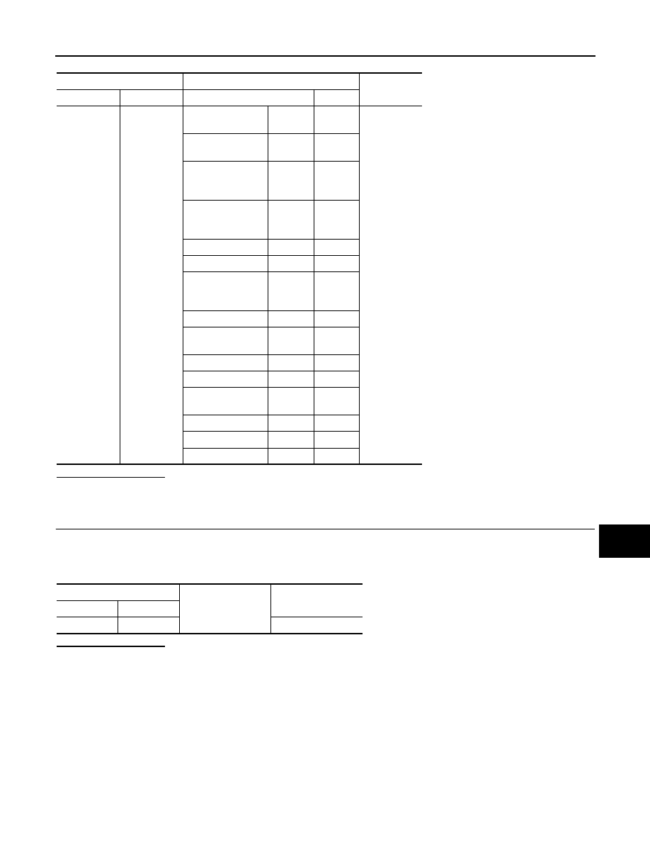
Check continuity between the total illumination control unit harness connector and ground.
Does continuity exist?
YES
>> Repair the harnesses or connectors.
NO
>> Replace the total illumination control unit.
Total illumination control unit
Illuminations
Continuity
Connector
Terminal
Connector
Terminal
M129
17
Meter control
switch
M54
5
Existed
Multifunction
switch
M72
5
Climate controlled
seat switch
(driver side)
M177
8
Climate controlled
seat switch
(passenger side)
M178
8
LDW switch
M29
4
Snow mode switch
M176
6
Door mirror
remote control
switch
M20
15
AFS OFF switch
M21
6
Headlamp aiming
switch
M15
4
Mode select switch
M179
2
Clock
M74
1
Combination
switch
M36
26
IBA OFF switch
M184
4
DCA switch
M18
4
VDC OFF switch
M19
4
Total illumination control unit
Ground
Continuity
Connector
Terminal
M129
17
Not existed
INL-58
< DTC/CIRCUIT DIAGNOSIS >
STEP LAMP CIRCUIT
STEP LAMP CIRCUIT
Description
INFOID:0000000005245598
Controls the step lamp (ground side) to turn the step lamp ON and OFF.
Component Function Check
INFOID:0000000005245599
CAUTION:
Check step lamp bulbs first.
1.
CHECK STEP LAMP OPERATION
CONSULT-III ACTIVE TEST
1.
Turn ignition switch ON.
2.
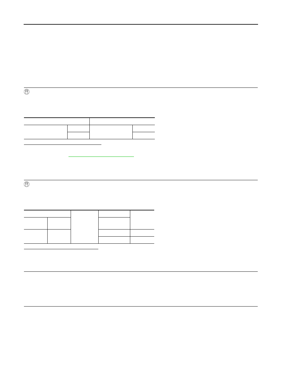
Select “STEP LAMP TEST” of BCM (INT LAMP) active test item.
3.
While operating the test items, check the step lamp operation.
Are the step lamps turned ON/OFF?
YES
>> Step lamp circuit is normal.
NO
>> Refer to
.
Diagnosis Procedure
INFOID:0000000005245600
1.
CHECK STEP LAMP OUTPUT
CONSULT-III ACTIVE TEST
1.
Turn ignition switch ON.
2.
Select “STEP LAMP TEST” of BCM (INT LAMP) active test item.
3.
While operating the test item, check continuity between BCM harness connector and ground.
Is the measurement value normal?
Fixed at 12 V>>Replace BCM.
Fixed at 0 V>>GO TO 2.
2.
CHECK THE SYMPTOM
Check that the lamp fixed to ON or OFF.
Fixed OFF>>GO TO 3.
Fixed ON>>GO TO 5.
3.
CHECK STEP LAMP POWER SUPPLY
1.
Turn ignition switch OFF.
2.
Disconnect the step lamp connector.
3.
Turn ignition switch ON.
4.
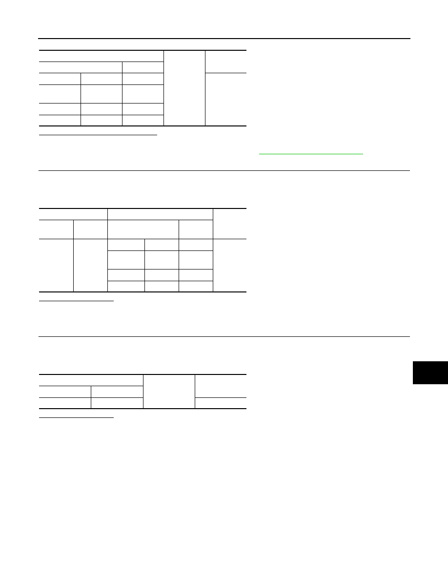
Check voltage between the step lamp harness connector and ground.
Test item
Operation
STEP LAMP TEST
On
Step lamps
ON
Off
OFF
BCM
Ground
Test item
Continuity
Connector
Terminal
STEP LAMP
TEST
M119
7
On
0 V
Off
12 V
STEP LAMP CIRCUIT
INL-59
< DTC/CIRCUIT DIAGNOSIS >
C
D
E
F
G
H
I
J
K
M
A
B
INL
N
O
P
Is the measurement value normal?
YES
>> GO TO 4.
NO
>> Check the interior room lamp power supply. Refer to
.
4.
CHECK STEP LAMP OPEN CIRCUIT
1.
Turn ignition switch OFF.
2.
Disconnect BCM connector.
3.
Check continuity between BCM harness connector and step lamp harness connector.
Does continuity exist?
YES
>> Replace the step lamp.
NO
>> Repair the harnesses or connectors.
5.
CHECK STEP LAMP SHORT CIRCUIT
1.
Turn ignition switch OFF.
2.
Disconnect BCM and step lamp connectors.
3.
Check continuity between BCM harness connector and ground.
Does continuity exist?
YES
>> Repair the harnesses or connectors.
NO
>> Replace BCM.
Step lamp
Ground
Voltage
(Approx.)
Connector
Terminal
Driver side
D12
1
12 V
Passenger
side
D42
1
Rear LH
D59
1
Rear RH
D79
1
BCM
Step lamp
Continuity
Connec-
tor
Terminal
Connector
Terminal
M119
7
Driver side
D12
2
Existed
Passenger
side
D42
2
Rear LH
D59
2
Rear RH
D79
2
BCM
Ground
Continuity
Connector
Terminal
M119
7
Not existed
Нет комментариевНе стесняйтесь поделиться с нами вашим ценным мнением.
Текст