Infiniti FX35, FX50 (S51). Manual — part 535
BACK DOOR
DLK-263
< REMOVAL AND INSTALLATION >
C
D
E
F
G
H
I
J
L
M
A
B
DLK
N
O
P
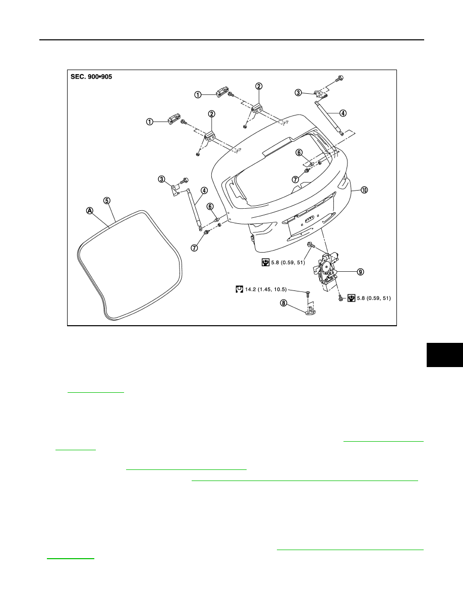
BACK DOOR HINGE : Exploded View
INFOID:0000000005239752
BACK DOOR HINGE : Removal and Installation
INFOID:0000000005239753
REMOVAL
1.
Remove luggage side lower finisher and luggage side upper finisher. Refer to
.
2.
Using a remover tool, remove headlining clip at the rear side of headlining, and then remove rear side of
headlining. Refer to
INT-24, "Removal and Installation"
.
3.
Remove back door assembly. Refer to
DLK-260, "BACK DOOR ASSEMBLY : Removal and Installation"
4.
Remove back door hinge mounting nuts (body side), and then remove back door hinge.
INSTALLATION
Install in the reverse order of removal.
CAUTION:
• Check back door hinge rotating part for poor lubrication. If necessary, apply body grease.
• After installation, check back door open/close, lock/unlock operation.
• After installation, perform the fitting adjustment. Refer to
DLK-261, "BACK DOOR ASSEMBLY :
1.
Back door hinge cover (LH/RH)
2.
Back door hinge (LH/RH)
3.
Back door stay bracket (LH/RH)
4.
Back door stay (LH/RH)
5.
Back door weather-strip
6.
Stud ball (LH/RH)
7.
Bumper rubber (side) (LH/RH)
8.
Back door striker
9.
Back door lock assembly
10. Back door assembly
A
: Center mark
Refer to
for symbols in the figure.
JMKIA2642GB
DLK-264
< REMOVAL AND INSTALLATION >
BACK DOOR
• After installation, perform the camera image calibration. Refer to
IMAGE (AROUND VIEW MONITOR) : Work Procedure"
CAMERA IMAGE (AROUND VIEW MONITOR) : Work Procedure"
(twin monitor).
BACK DOOR STAY
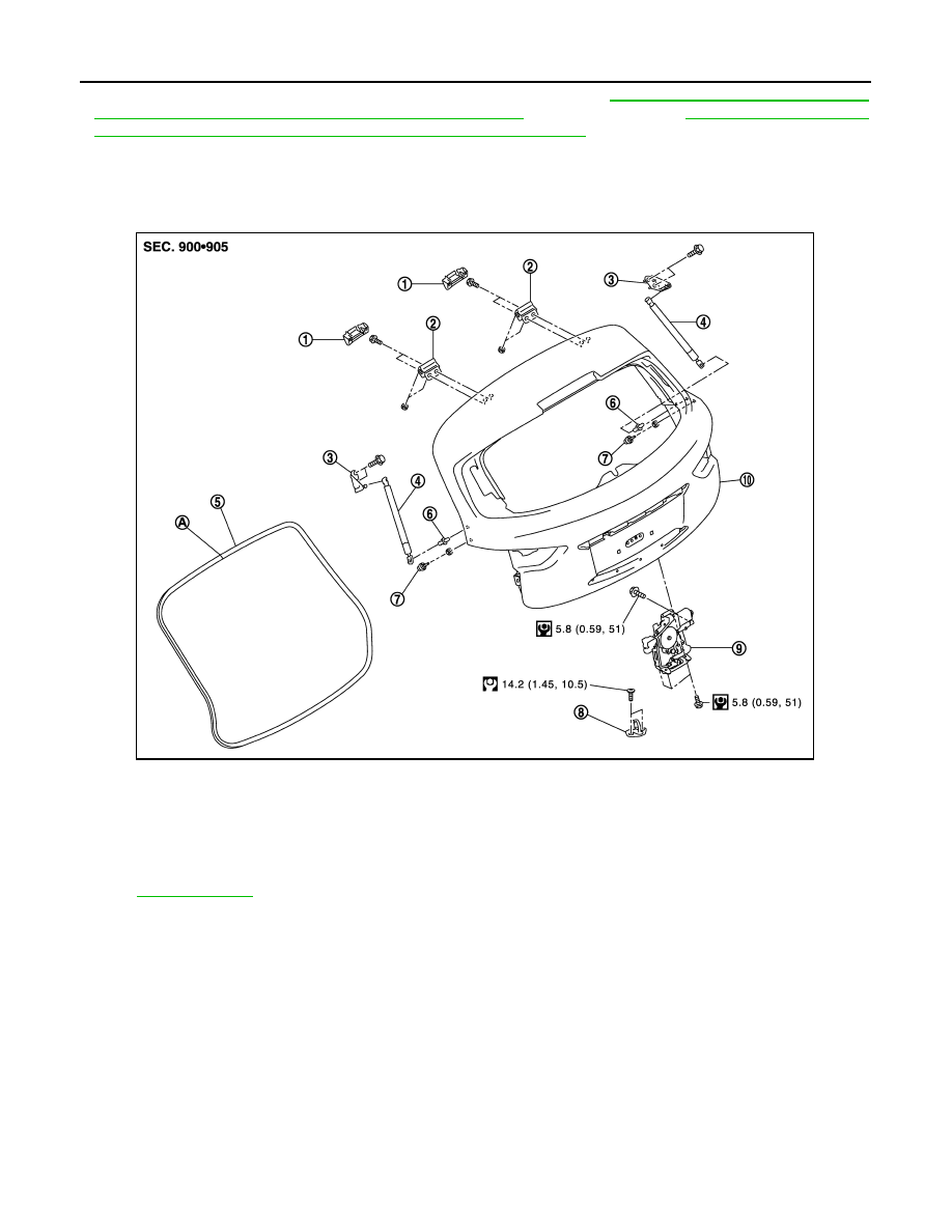
BACK DOOR STAY : Exploded View
INFOID:0000000005239754
BACK DOOR STAY : Removal and Installation
INFOID:0000000005239755
REMOVAL
1.
Support back door lock with the proper material to prevent it from falling.
WARNING:
Bodily injury may occur if no supporting rod is holding the back door open when removing the
back door stay.
2.
Remove mounting bolts of back door stay (body side).
1.
Back door hinge cover (LH/RH)
2.
Back door hinge (LH/RH)
3.
Back door stay bracket (LH/RH)
4.
Back door stay (LH/RH)
5.
Back door weather-strip
6.
Stud ball (LH/RH)
7.
Bumper rubber (side) (LH/RH)
8.
Back door striker
9.
Back door lock assembly
10. Back door assembly
A
: Center mark
Refer to
for symbols in the figure.
JMKIA2642GB
BACK DOOR
DLK-265
< REMOVAL AND INSTALLATION >
C
D
E
F
G
H
I
J
L
M
A
B
DLK
N
O
P
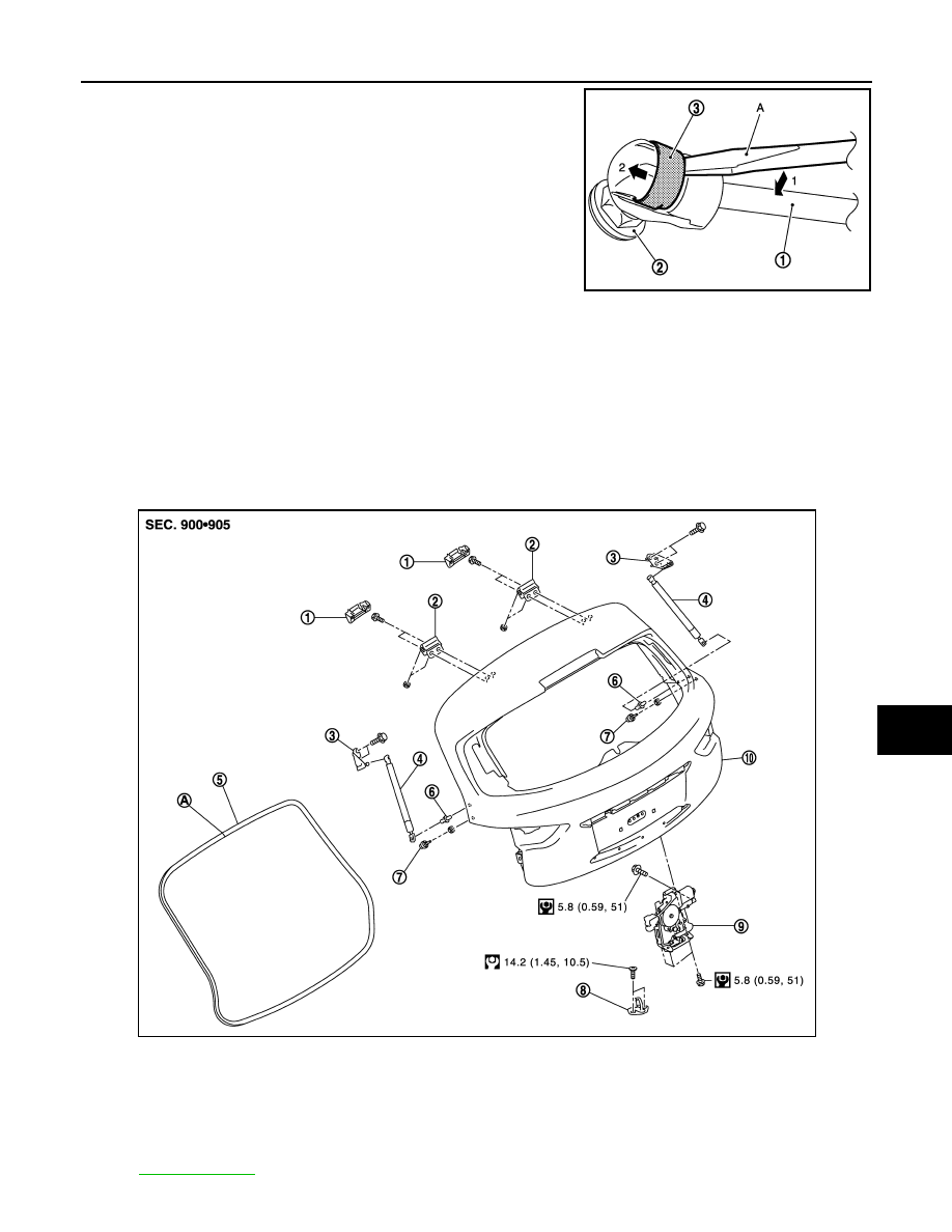
3.
Remove the metal clip (3) located on the connection between
the back door stay (1) and the stud ball (2) (back door side) by
using a flat-bladed screwdriver (A).
4.
Remove back door stay (back door side).
5.
Remove mounting bolts of back door stay bracket, and then remove stud ball assembly.
INSTALLATION
Install in the reverse order of removal.
CAUTION:
After installation, check back door open/close operation.
BACK DOOR WEATHER-STRIP
BACK DOOR WEATHER-STRIP : Exploded View
INFOID:0000000005239756
JMKIA2255ZZ
1.
Back door hinge cover (LH/RH)
2.
Back door hinge (LH/RH)
3.
Back door stay bracket (LH/RH)
4.
Back door stay (LH/RH)
5.
Back door weather-strip
6.
Stud ball (LH/RH)
7.
Bumper rubber (side) (LH/RH)
8.
Back door striker
9.
Back door lock assembly
10. Back door assembly
A
: Center mark
Refer to
for symbols in the figure.
JMKIA2642GB
DLK-266
< REMOVAL AND INSTALLATION >
BACK DOOR
BACK DOOR WEATHER-STRIP : Removal and Installation
INFOID:0000000005239757
REMOVAL
Pull up and remove engagement with body from weather-strip joint.
CAUTION:
Never pull strongly on weather-strip.
INSTALLATION
1.
Working from the upper section, align weather-strip center mark with vehicle center position mark and
install weather-strip onto the vehicle.
2.
Pull weather-strip gently to ensure that there is no loose section.
NOTE:
Check that weather-strip fits tightly in each corner and luggage rear plate.
Нет комментариевНе стесняйтесь поделиться с нами вашим ценным мнением.
Текст