Infiniti FX35, FX50 (S51). Manual — part 536
HOOD LOCK
DLK-267
< REMOVAL AND INSTALLATION >
C
D
E
F
G
H
I
J
L
M
A
B
DLK
N
O
P
HOOD LOCK
Exploded View
INFOID:0000000005239758
Removal and Installation
INFOID:0000000005239759
REMOVAL
CAUTION:
Before removal, confirm how the hood lock control cable is allocated and connected.
1.
Remove air duct (inlet). Refer to
2.
Remove engine room cover (LH/RH) (VK50VE models). Refer to
EM-175, "Removal and Installation"
.
3.
Remove air cleaner case assembly (RH). Refer to
EM-29, "Removal and Installation"
.
4.
Disconnect hood switch connector from head lamp bracket (RH).
5.
Remove mounting bolts and remove hood lock bracket (LH/RH).
6.
Disconnect hood lock control cable (front) from hood lock (LH/RH).
7.
Disassembly hood lock from hood lock bracket (LH/RH).
8.
Remove fender protector (LH). Refer to
EXT-25, "FENDER PROTECTOR : Removal and Installation"
9.
Remove clips of hood seal assembly (side) (LH) at the front side.
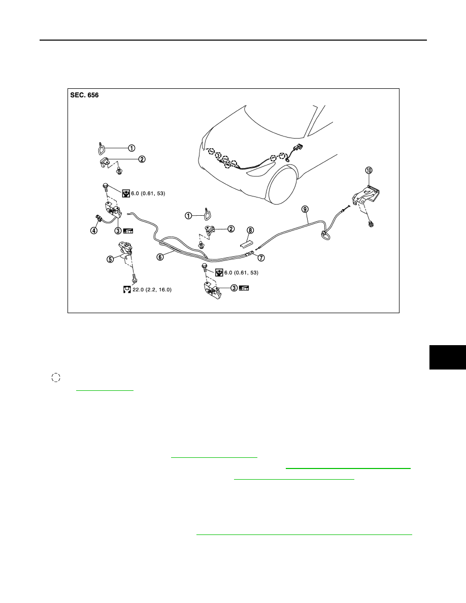
1.
Hood striker (LH/RH)
2.
Hood lock cover (LH/RH)
3.
Hood lock (LH/RH)
4.
Hood switch
5.
Secondary latch
6.
Hood lock control cable (front)
7.
Hood lock control cable protector
8.
Hood lock control cable protector
cover
9.
Hood lock control cable (rear)
10. Hood lock opener
: Clip
Refer to
JMKIA2644GB
DLK-268
< REMOVAL AND INSTALLATION >
HOOD LOCK
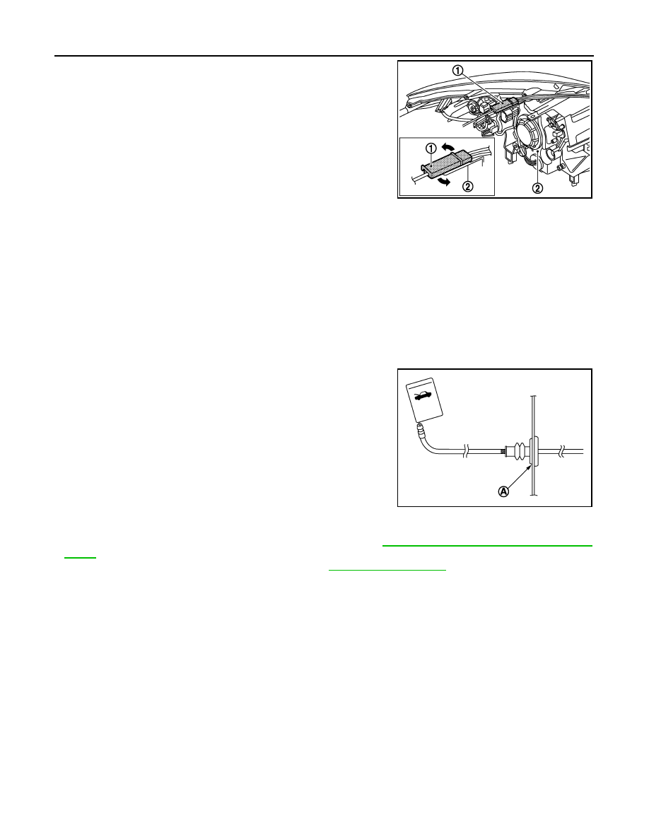
10. Rotate hood lock control cable protector (1) toward the arrow
direction, then remove it from front combination lamp assembly
(2).
11. Remove hood lock control cable protector cover from hood lock control cable protector.
12. Disconnect hood lock control cable (rear) from hood lock control cable protector.
13. Remove mounting bolts and remove hood lock opener.
14. Remove grommet on the lower dash, pull hood lock control cable (rear) toward the passenger compart-
ment.
CAUTION:
While pulling, never damage (peeling) the outside of the hood lock control cable.
INSTALLATION
Install in the reverse order of removal.
CAUTION:
• Never bend cable too much. Keep the radius 100 mm (3.937 in) or more.
• Check cable is not offset from the positioning grommet, and
apply the sealant to the grommet (A) properly.
• Check hood lock control cable is properly engaged with hood lock.
• After installation, perform the fitting adjustment. Refer to
DLK-238, "HOOD ASSEMBLY : Adjust-
• After installation, perform the inspection. Refer to
.
Inspection
INFOID:0000000005239760
NOTE:
If the hood lock cable is bent or deformed, replace it.
1.
Check that secondary latch is properly engaged with secondary striker [6.8 mm (0.268 in)] by hood
weight.
2.
While operating hood opener, carefully check that the front end of hood is raised by approximately 20 mm
(0.787 in). Also check that hood opener returns to the original position.
3.
Check that hood opener operating is condition 49 N (5.0 kg, 11.0 lb) or less.
4.
Install so that static closing force of hood is 94 – 490 N (9.6 – 50.0 kg, 21.1 – 110 lb).
NOTE:
• Exert vertical force on right side and left side of hood lock.
• Do not simultaneously press both sides.
5.
Check the hood lock lubrication condition. If necessary, apply body grease to hood lock.
JMKIA2647ZZ
JMKIA2398ZZ
FRONT DOOR LOCK
DLK-269
< REMOVAL AND INSTALLATION >
C
D
E
F
G
H
I
J
L
M
A
B
DLK
N
O
P
FRONT DOOR LOCK
DOOR LOCK
DOOR LOCK : Exploded View
INFOID:0000000005239761
DOOR LOCK : Removal and Installation
INFOID:0000000005239762
REMOVAL
1.
Remove front door finisher. Refer to
INT-11, "Removal and Installation"
2.
Remove front door glass. Refer to
GW-18, "Removal and Installation"
3.
Remove front door module assembly. Refer to
GW-21, "Removal and Installation"
.
4.
Remove door key cylinder assembly (outside handle escutcheon), outside handle, outside handle bracket,
rear gasket and front gasket. Refer to
DLK-271, "OUTSIDE HANDLE : Removal and Installation"
5.
Remove door lock assembly TORX bolts.
6.
Disconnect door lock actuator connector, and then remove door lock assembly.
7.
Remove key rod from door lock assembly.
INSTALLATION
Install in the reverse order of removal.
CAUTION:
• Check door lock cables are properly engaged with inside handle and outside handle.
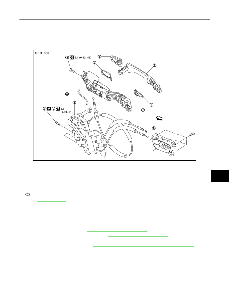
1.
Door key cylinder assembly (driver
side)
Outside handle escutcheon (passen-
ger side)
2.
Rear gasket
3.
TORX bolt
4.
Key rod (driver side)
5.
Door lock assembly
6.
Inside handle
7.
Outside handle bracket
8.
Front gasket
9.
Outside handle
: Vehicle front
Refer to
JMKIA2917GB
DLK-270
< REMOVAL AND INSTALLATION >
FRONT DOOR LOCK
• When installing key rod, rotate key rod holder until a click is felt.
• After installation, check door open/close, lock/unlock operation.
INSIDE HANDLE
INSIDE HANDLE : Exploded View
INFOID:0000000005239763
INSIDE HANDLE : Removal and Installation
INFOID:0000000005239764
REMOVAL
1.
Remove front door finisher. Refer to
INT-11, "Removal and Installation"
2.
Disconnect door lock cables from inside handle.
3.
Remove inside handle mounting screws, and then remove the inside handle.
INSTALLATION
Install in the reverse order of removal.
CAUTION:
• Check door lock cables are properly engaged with inside handle.
• After installation, check door open/close, lock/unlock operation.
OUTSIDE HANDLE
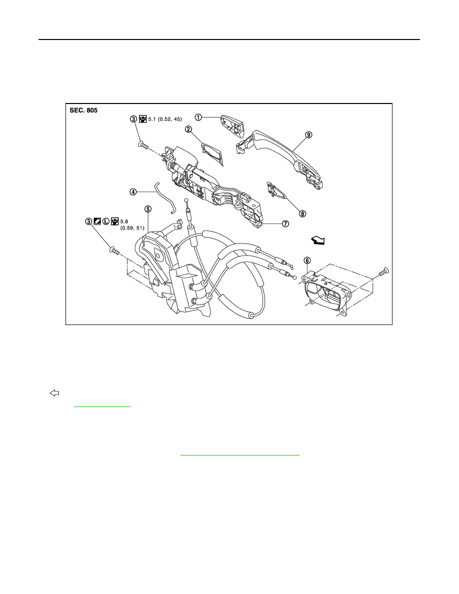
1.
Door key cylinder assembly (driver
side)
Outside handle escutcheon (passen-
ger side)
2.
Rear gasket
3.
TORX bolt
4.
Key rod (driver side)
5.
Door lock assembly
6.
Inside handle
7.
Outside handle bracket
8.
Front gasket
9.
Outside handle
: Vehicle front
Refer to
for symbols in the figure.
JMKIA2917GB
Нет комментариевНе стесняйтесь поделиться с нами вашим ценным мнением.
Текст