Infiniti FX35, FX50 (S51). Manual — part 534
BACK DOOR
DLK-259
< REMOVAL AND INSTALLATION >
C
D
E
F
G
H
I
J
L
M
A
B
DLK
N
O
P
BACK DOOR
BACK DOOR ASSEMBLY
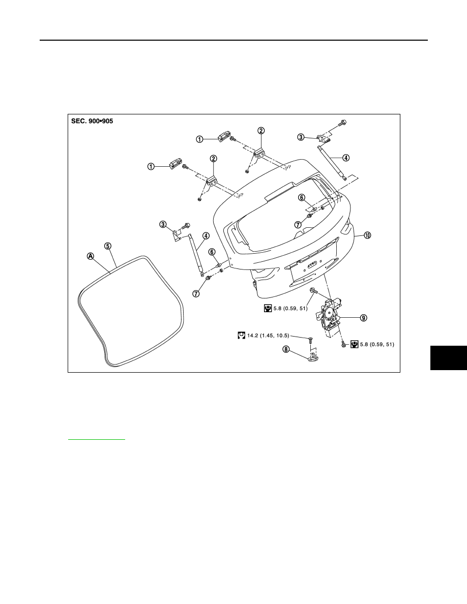
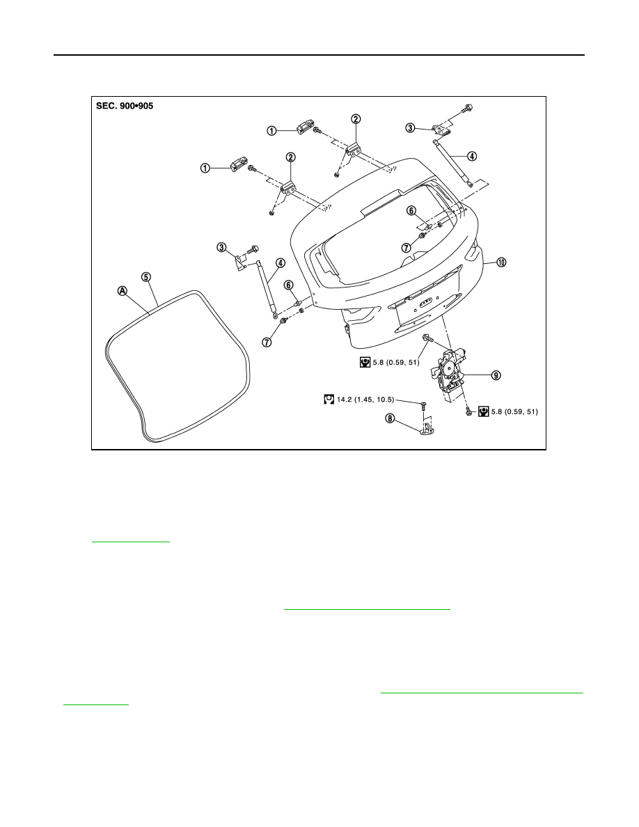
BACK DOOR ASSEMBLY : Exploded View
INFOID:0000000005239747
REMOVAL
ADJUSTMENT
1.
Back door hinge cover (LH/RH)
2.
Back door hinge (LH/RH)
3.
Back door stay bracket (LH/RH)
4.
Back door stay (LH/RH)
5.
Back door weather-strip
6.
Stud ball (LH/RH)
7.
Bumper rubber (LH/RH)
8.
Back door striker
9.
Back door lock assembly
10. Back door assembly
A
: Center mark
Refer to
for symbols in the figure.
JMKIA2642GB

DLK-260
< REMOVAL AND INSTALLATION >
BACK DOOR
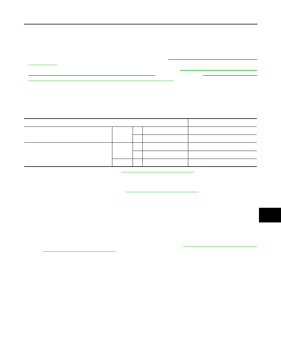
BACK DOOR ASSEMBLY : Removal and Installation
INFOID:0000000005239748
CAUTION:
• Operate with two workers, because of its heavy weight.
• Use protective tape or shop cloth to protect from damage during removal and installation.
NOTE:
The back door harness constitute the back door assembly.
REMOVAL
1.
Remove back door finisher inner, back door plate and back door hinge cover. Refer to
2.
Remove clips of headlining at rear end. Refer to
INT-24, "Removal and Installation"
.
3.
Disconnect connectors and bolts of back door harness.
4.
Remove back door grommet (LH), and then pull harness out of vehicle at roof panel hole.
5.
Remove back door plate, and then disconnect washer tube. Refer to
129, "Removal and Installation"
6.
Pull washer tube out of back door.
7.
Support back door lock with the proper material to prevent it from falling.
WARNING:
Bodily injury may occur if no supporting rod is holding the back door open when removing the
back door stay.
8.
Remove back door stay. Refer to
DLK-264, "BACK DOOR STAY : Removal and Installation"
.
9.
Remove back door hinge mounting bolts on back door and remove back door assembly.
1.
Back door assembly
2.
Bumper rubber
3.
Back door hinge
4.
Back door striker
5.
Roof
6.
Rear bumper fascia
Refer to
for symbols in the figure.
JMKIA2643GB
BACK DOOR
DLK-261
< REMOVAL AND INSTALLATION >
C
D
E
F
G
H
I
J
L
M
A
B
DLK
N
O
P
INSTALLATION
Install in the reverse order of removal.
CAUTION:
• Check back door hinge rotating part for poor lubrication. If necessary, apply body grease.
• After installation, check back door open/close, lock/unlock operation.
• After installation, perform the fitting adjustment. Refer to
DLK-261, "BACK DOOR ASSEMBLY :
• After installation, perform the camera image calibration. Refer to
IMAGE (AROUND VIEW MONITOR) : Work Procedure"
(single monitor) or
CAMERA IMAGE (AROUND VIEW MONITOR) : Work Procedure"
(twin monitor).
BACK DOOR ASSEMBLY : Adjustment
INFOID:0000000005239749
Check the clearance and the surface height between back door and each part by seeing and touching.
If the clearance and the surface height are out of specification, adjust them according to the procedures
shown below.
Unit: mm (in)
1.
Remove back door hinge cover. Refer to
INT-32, "Removal and Installation"
2.
Loosen back door hinge mounting bolts (back door side).
3.
Loosen bumper rubber.
4.
Remove luggage rear plate mask. Refer to
INT-29, "Removal and Installation"
5.
Loosen back door striker mounting bolts.
6.
Lift up back door approximately 100 – 150 mm (3.937 – 5.906 in) height then close it lightly and check that
it is engaged firmly with back door closed.
7.
Check the clearance and surface height.
8.
Finally tighten back door hinge, bumper rubber, and back door striker.
CAUTION:
• Check back door hinge rotating part for poor lubrication. If necessary, apply body grease.
• After installation, check back door open/close, lock/unlock operation.
9.
Install back door hinge cover and luggage rear plate mask. Refer to
INT-32, "Removal and Installation"
INT-29, "Removal and Installation"
.
BACK DOOR STRIKER ADJUSTMENT
Adjust back door striker so that it becomes parallel with back door lock insertion direction.
BACK DOOR STRIKER
Portion
Standard
Back door – Roof
A – A
D
Clearance
5.0 – 9.0 (0.197 – 0.354)
E
Surface height
−
0.4 – 3.6 (
−
0.016 – 0.142)
Back door – Rear bumper fascia
B – B
F
Clearance
3.0 – 7.0 (0.118 – 0.276)
G
Surface height
−
2.1 – 2.1 (
−
0.083 – 0.083)
C – C
H
Clearance
5.0 – 9.0 (0.197 – 0.354)
DLK-262
< REMOVAL AND INSTALLATION >
BACK DOOR
BACK DOOR STRIKER : Exploded View
INFOID:0000000005239750
BACK DOOR STRIKER : Removal and Installation
INFOID:0000000005239751
REMOVAL
1.
Remove luggage rear plate mask. Refer to
INT-29, "Removal and Installation"
2.
Remove mounting bolts, and then remove back door striker.
INSTALLATION
Install in the reverse order of removal.
CAUTION:
• After installation, check back door open/close, lock/unlock operation.
• After installation, perform the fitting adjustment. Refer to
DLK-261, "BACK DOOR ASSEMBLY :
BACK DOOR HINGE
1.
Back door hinge cover (LH/RH)
2.
Back door hinge (LH/RH)
3.
Back door stay bracket (LH/RH)
4.
Back door stay (LH/RH)
5.
Back door weather-strip
6.
Stud ball (LH/RH)
7.
Bumper rubber (side) (LH/RH)
8.
Back door striker
9.
Back door lock assembly
10. Back door assembly
A
: Center mark
Refer to
for symbols in the figure.
JMKIA2642GB
Нет комментариевНе стесняйтесь поделиться с нами вашим ценным мнением.
Текст