Infiniti FX35, FX50 (S51). Manual — part 1842
AIR BREATHER HOSE
TM-175
< REMOVAL AND INSTALLATION >
[7AT: RE7R01A (VQ35HR)]
C
E
F
G
H
I
J
K
L
M
A
B
TM
N
O
P
AWD
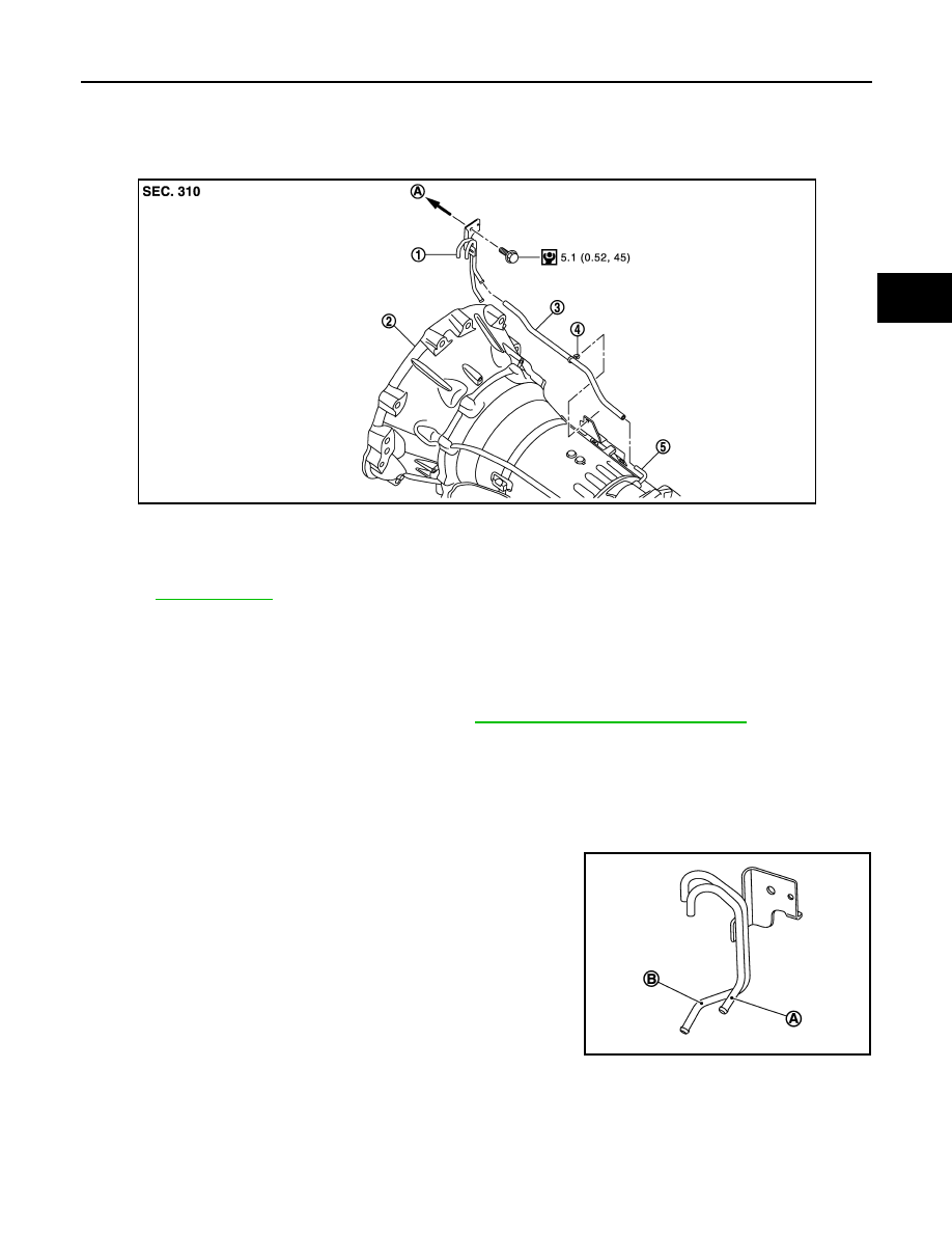
AWD : Exploded View
INFOID:0000000005250164
AWD : Removal and Installation
INFOID:0000000005250165
REMOVAL
1.
Remove air breather vent from water outlet (rear).
2.
Remove propeller shaft assembly (front). Refer to
DLN-109, "VQ35HR : Exploded View"
.
3.
Remove air breather hose.
INSTALLATION
Note the following, and install in the reverse order of removal.
CAUTION:
• When installing air breather hose, be careful not to be crushed or blocked by folding or bending the
hose.
• When inserting air breather hose to the air breather vent (for
A/T) (A), be sure to insert it fully until its end reaches the tube
bend “R” portion.
• Install air breather hose to air breather vent (for A/T) so that
the paint mark is facing upward.
• Ensure clips are securely installed to brackets when installing
air breather hose to brackets.
1.
Air breather vent
2.
A/T assembly
3.
Air breather hose
4.
Clip
5.
Air breather tube
A.
To water outlet (rear)
Refer to
JSDIA1459GB
B
: Air breather vent (for transfer)
JSDIA1460ZZ
TM-176
< REMOVAL AND INSTALLATION >
[7AT: RE7R01A (VQ35HR)]
FLUID COOLER SYSTEM
FLUID COOLER SYSTEM
2WD
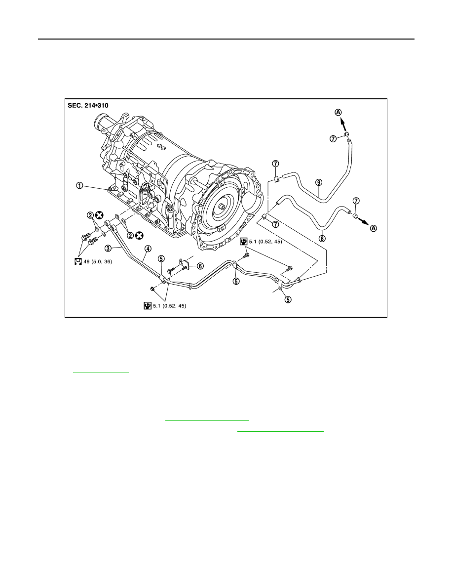
2WD : Exploded View
INFOID:0000000005250166
2WD : Removal and Installation
INFOID:0000000005250167
REMOVAL
1.
Remove air duct (inlet). Refer to
2.
Remove engine lower cover with power tool. Refer to
.
3.
Remove A/T fluid cooler hose A and A/T fluid cooler hose B.
4.
Remove A/T fluid cooler tubes from A/T assembly and engine.
5.
Plug up opening such as the A/T fluid cooler tube hole.
6.
Remove A/T fluid cooler tubes from the vehicle.
CAUTION:
Be careful not to bend A/T fluid cooler tubes.
7.
Remove clips and bracket.
INSTALLATION
Note the following, and install in the reverse order of removal.
CAUTION:
Never reuse copper washer.
• Refer to the following when installing A/T fluid cooler hoses.
1.
A/T assembly
2.
Copper washer
3.
A/T fluid cooler tube
4.
A/T fluid cooler tube
5.
Clip
6.
Bracket
7.
Hose clamp
8.
A/T fluid cooler hose B
9.
A/T fluid cooler hose A
A.
To radiator
Refer to
for symbols in the figure.
JPDIA0856GB
FLUID COOLER SYSTEM
TM-177
< REMOVAL AND INSTALLATION >
[7AT: RE7R01A (VQ35HR)]
C
E
F
G
H
I
J
K
L
M
A
B
TM
N
O
P
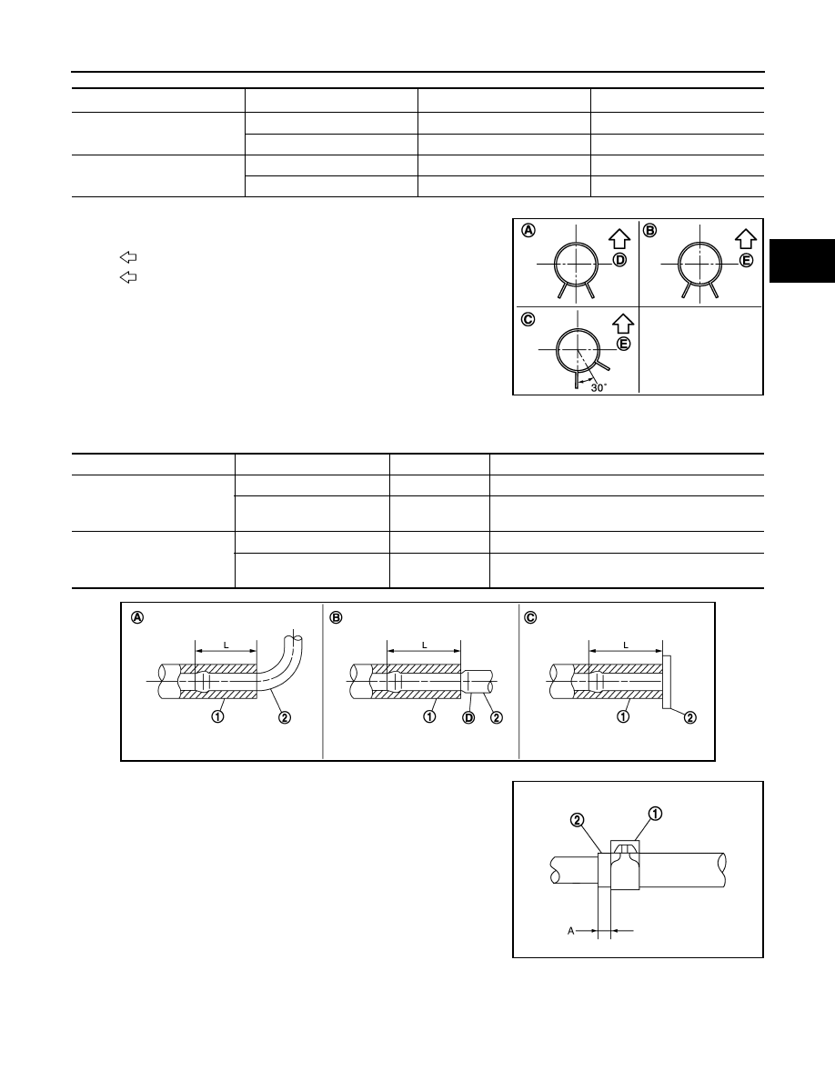
*: Refer to the illustrations for the specific position each hose clamp tab.
- The illustrations indicate the view from the hose ends.
- When installing hose clamps center line of each hose clamp tab
should be positioned as shown in the figure.
- Insert A/T fluid cooler hoses according to dimension “L” described below.
- Set hose clamps (1) at the both ends of A/T fluid cooler hoses (2)
with dimension “A” from the hose edge.
- Hose clamp should not interfere with the bulge of fluid cooler tube.
2WD : Inspection and Adjustment
INFOID:0000000005250168
INSPECTION AFTER INSTALLATION
Check A/T fluid leakage.
Hose name
Hose end
Paint mark
Position of hose clamp
*
A/T fluid cooler hose A
Radiator assembly side
Facing backward
A
A/T fluid cooler tube side
Facing downward
B
A/T fluid cooler hose B
Radiator assembly side
Facing downward
C
A/T fluid cooler tube side
Facing downward
B
D
: Vehicle front
E
: Vehicle upper
JSDIA0795ZZ
(1)
(2)
Tube type
Dimension “L”
A/T fluid cooler hose A
Radiator assembly side
A
End reaches the radius curve end.
A/T fluid cooler tube side
B
30 mm (1.18 in) [End reaches the 2-stage bulge
(D).]
A/T fluid cooler hose B
Radiator assembly side
C
Insert the hose until the hose touches the radiator.
A/T fluid cooler tube side
B
30 mm (1.18 in) [End reaches the 2-stage bulge
(D).]
JSDIA0882ZZ
Dimension “A”
: 5 – 9 mm (0.20 – 0.35 in)
SCIA8123E
TM-178
< REMOVAL AND INSTALLATION >
[7AT: RE7R01A (VQ35HR)]
FLUID COOLER SYSTEM
ADJUSTMENT AFTER INSTALLATION
Adjust A/T fluid level. Refer to
AWD
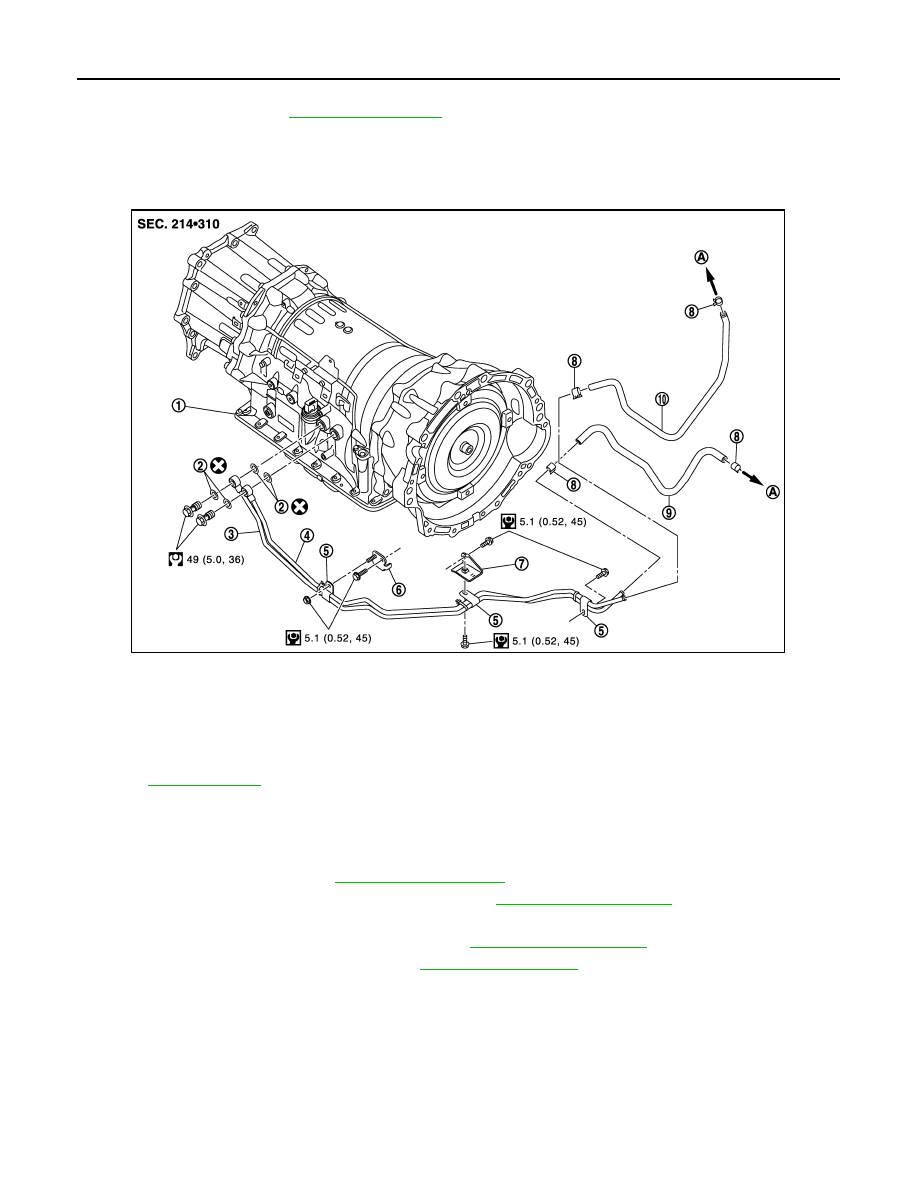
AWD : Exploded View
INFOID:0000000005250169
AWD : Removal and Installation
INFOID:0000000005250170
REMOVAL
1.
Remove air duct (inlet). Refer to
2.
Remove engine under cover with a power tool. Refer to
.
3.
Remove A/T fluid cooler hose A and A/T fluid cooler hose B.
4.
Remove control rod from A/T shift selector. Refer to
.
5.
Remove exhaust mounting bracket. Refer to
1.
A/T assembly
2.
Copper washer
3.
A/T fluid cooler tube
4.
A/T fluid cooler tube
5.
Clip
6.
Bracket
7.
Bracket
8.
Hose clamp
9.
A/T fluid cooler hose B
10. A/T fluid cooler hose A
A.
To radiator
Refer to
for symbols in the figure.
JPDIA0854GB
Нет комментариевНе стесняйтесь поделиться с нами вашим ценным мнением.
Текст