Infiniti FX35, FX50 (S51). Manual — part 1841
CONTROL ROD
TM-171
< REMOVAL AND INSTALLATION >
[7AT: RE7R01A (VQ35HR)]
C
E
F
G
H
I
J
K
L
M
A
B
TM
N
O
P
CONTROL ROD
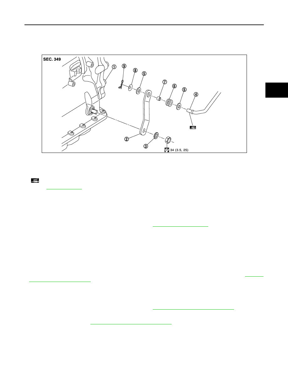
Exploded View
INFOID:0000000005250154
Removal and Installation
INFOID:0000000005250155
REMOVAL
1.
Shift the selector lever to “P” position.
2.
Disconnect A/T shift selector and control rod. Refer to
.
3.
Remove manual lever from A/T assembly.
4.
Remove control rod from manual lever.
INSTALLATION
Note the following, and install in the reverse order of removal.
CAUTION:
Apply multi-purpose grease on the pin surface (that slides after installing collar) of the tip of the con-
trol rod.
• When installing control rod to A/T shift selector assembly, refer to “ADJUSTMENT”. Refer to
.
Inspection and Adjustment
INFOID:0000000005250156
INSPECTION AFTER INSTALLATION
Check A/T positions after adjusting A/T positions. Refer to
TM-349, "Inspection and Adjustment"
ADJUSTMENT AFTER INSTALLATION
Adjust A/T positions. Refer to
TM-349, "Inspection and Adjustment"
1.
A/T assembly
2.
Manual lever
3.
Lock washer
4.
Control rod
5.
Washer
6.
Insulator
7.
Collar
8.
Conical washer
9.
Snap pin
: Apply multi-purpose grease.
for symbols not described on the above.
JSDIA1002GB

TM-172
< REMOVAL AND INSTALLATION >
[7AT: RE7R01A (VQ35HR)]
OIL PAN
OIL PAN
Exploded View
INFOID:0000000005250159
Removal and Installation
INFOID:0000000005250160
REMOVAL
1.
Drain ATF through drain plug.
2.
Remove exhaust mounting bracket. Refer to
3.
Disconnect heated oxygen sensor 2 harness connectors (A).
4.
Remove heated oxygen sensor 2 harness (B) from clips (1).
5.
Remove bracket (2) from A/T assembly. Refer to
(2WD),
(AWD).
1.
A/T
2.
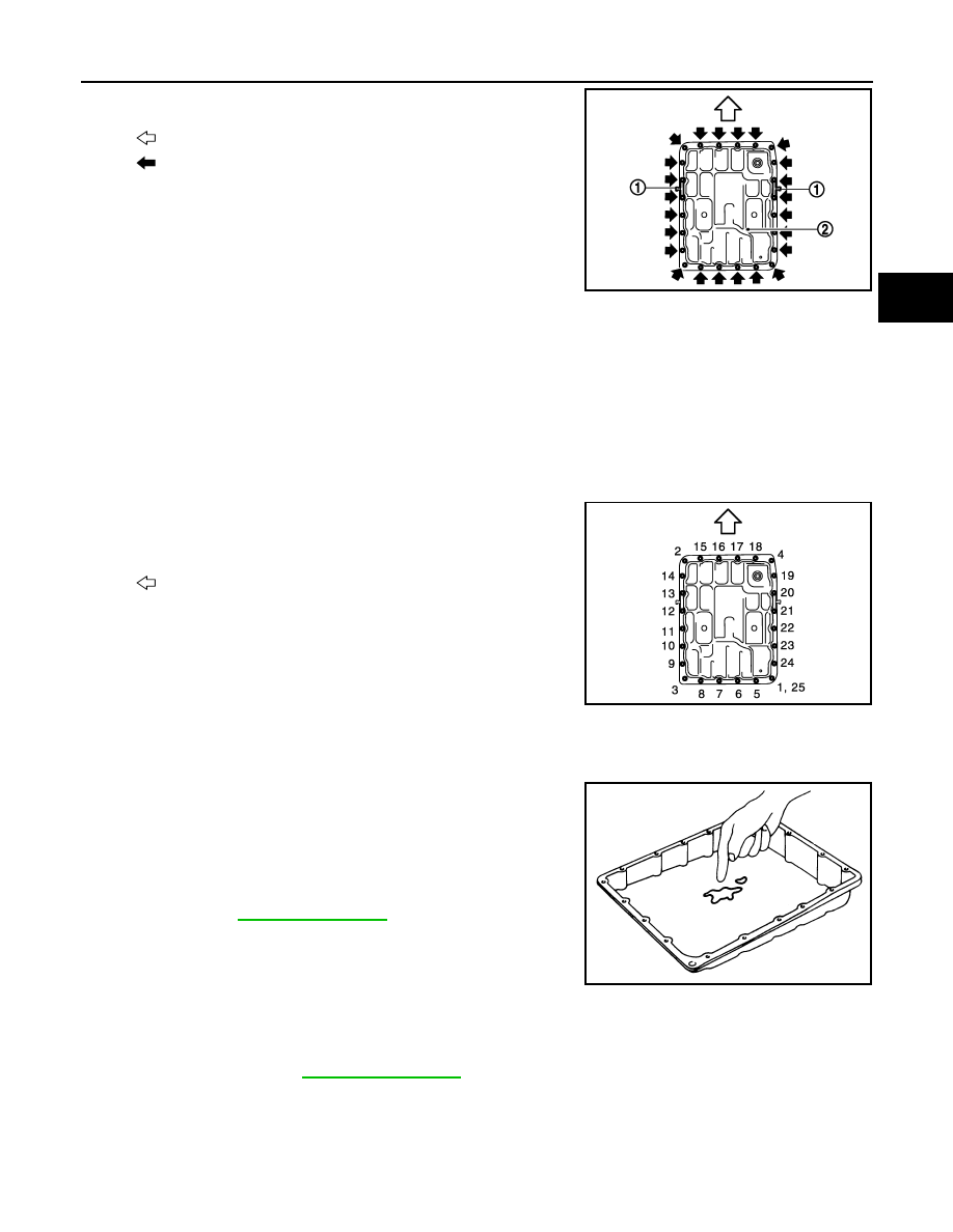
Oil pan gasket
3.
Oil pan
4.
Clip
5.
Oil pan mounting bolt
6.
Overflow plug
7.
Drain plug
8.
Drain plug gasket
9.
Magnet
Refer to
for symbols in the figure.
JPDIA0853GB
: Vehicle front
: Bolt
SCIA8269E
OIL PAN
TM-173
< REMOVAL AND INSTALLATION >
[7AT: RE7R01A (VQ35HR)]
C
E
F
G
H
I
J
K
L
M
A
B
TM
N
O
P
6.
Remove clips (1).
7.
Remove oil pan (2) and oil pan gasket.
8.
Remove magnets from oil pan.
INSTALLATION
Note the following, and install in the reverse order of removal.
CAUTION:
• Clean foreign materials (gear wear particles) that adhere on the inside of the oil pan and on the mag-
net, and then assembly.
• Completely remove all moisture, oil and old gasket, etc. from oil pan gasket mounting surface of
transmission case and oil pan.
• Never reuse oil pan gasket and oil pan mounting bolts.
• Install oil pan gasket in the direction to align hole position.
• Never reuse drain plug and drain plug gasket. In addition, install new drain plug and drain plug gas-
ket after adjustment of A/T fluid filling.
• Tighten the oil pan mounting bolts to the specified torque in the
numerical order as shown in the figure after temporarily tightening
them.
Inspection and Adjustment
INFOID:0000000005250161
INSPECTION AFTER REMOVAL
Check foreign materials in oil pan to help determine causes of mal-
function. If the ATF is very dark, smells burned, or contains foreign
particles, the frictional material (clutches, band) may need replace-
ment. A tacky film that will not wipe clean indicates varnish build up.
Varnish can cause valves, servo, and clutches to stick and can
inhibit pump pressure.
• If frictional material is detected, perform A/T fluid cooler
cleaning. Refer to
.
INSPECTION AFTER INSTALLATION
Check A/T fluid leakage.
ADJUSTMENT AFTER INSTALLATION
Adjust A/T fluid level. Refer to
: Vehicle front
: Oil pan mounting bolt
JSDIA0793ZZ
: Vehicle front
JSDIA0794ZZ
SCIA5199E
TM-174
< REMOVAL AND INSTALLATION >
[7AT: RE7R01A (VQ35HR)]
AIR BREATHER HOSE
AIR BREATHER HOSE
2WD
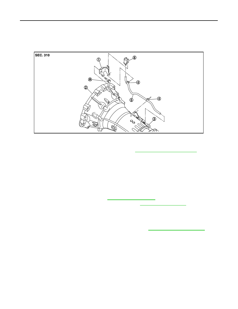
2WD : Exploded View
INFOID:0000000005250162
2WD : Removal and Installation
INFOID:0000000005250163
REMOVAL
1.
Remove clips from brackets.
2.
Remove air breather box from bracket.
3.
Remove air breather box from air breather hose.
4.
Remove air breather hose.
5.
Separate propeller shaft assembly. Refer to
6.
Remove control rod from A/T shift selector assembly. Refer to
7.
Support A/T assembly with a transmission jack.
CAUTION:
When setting the transmission jack, be careful not to allow it to collide against the drain plug and
overflow plug.
8.
Remove rear engine mounting member with a power tool. Refer to
9.
Remove bolt fixing A/T assembly to engine with a power tool.
10. Remove bracket.
INSTALLATION
Note the following, and install in the reverse order of removal.
CAUTION:
• When installing air breather hose, be careful not to crushed or blocked by folding or bending the
hose.
• When inserting air breather hose to air breather tube, be sure to insert it fully until its end reaches
the radius curve end.
• When inserting air breather hose to air breather box, be sure to insert it fully until its end reaches the
stop.
• Install air breather hose to air breather box so that the paint mark is facing backward.
• Ensure clips are securely installed to brackets when installing air breather hose to brackets.
1.
Bracket
2.
A/T assembly
3.
Air breather tube
4.
Clip
5.
Air breather hose
6.
A/T breather box
A.
Tightening must be done following the installation procedure. Refer to
TM-174, "2WD : Removal and Installation"
JSDIA1112ZZ
Нет комментариевНе стесняйтесь поделиться с нами вашим ценным мнением.
Текст