Infiniti FX35, FX50 (S51). Manual — part 1843
FLUID COOLER SYSTEM
TM-179
< REMOVAL AND INSTALLATION >
[7AT: RE7R01A (VQ35HR)]
C
E
F
G
H
I
J
K
L
M
A
B
TM
N
O
P
6.
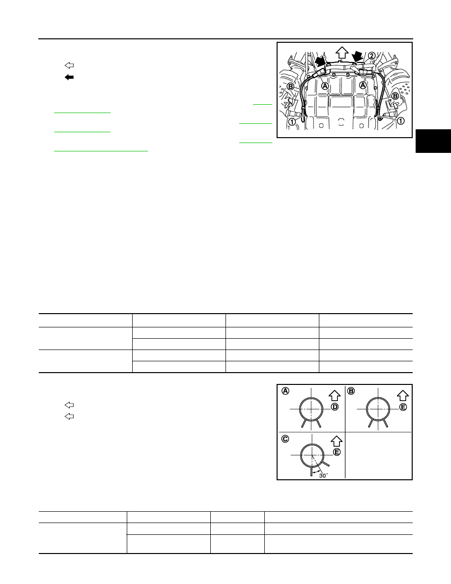
Disconnect heated oxygen sensor 2 connectors (A).
7.
Remove heated oxygen sensor 2 harness (B) from clips (1).
8.
Remove harness bracket (2) from A/T assembly. Refer to
9.
Remove propeller shaft assembly (rear). Refer to
10. Remove propeller shaft assembly (front). Refer to
11. Lift up a transmission jack to make the gap between converter housing of A/T assembly and front suspen-
sion member.
CAUTION:
Never contact the A/T and transfer assembly with the lower lever of A/T shift selector when lifting
up a transmission jack.
12. Remove A/T fluid cooler tubes from A/T assembly and engine.
13. Plug up opening such as the A/T fluid cooler tube hole.
14. Remove clips and brackets.
15. Remove A/T fluid cooler tubes from the vehicle.
CAUTION:
Be careful not to bend A/T fluid cooler tubes.
INSTALLATION
Note the following, and install in the reverse order of removal.
CAUTION:
Never reuse copper washer.
• Refer to the following when installing A/T fluid cooler hoses.
*: Refer to the illustrations for the specific position each hose clamp tab.
- The illustrations indicate the view from the hose ends.
- When installing hose clamps center line of each hose clamp tab
should be positioned as shown in the figure.
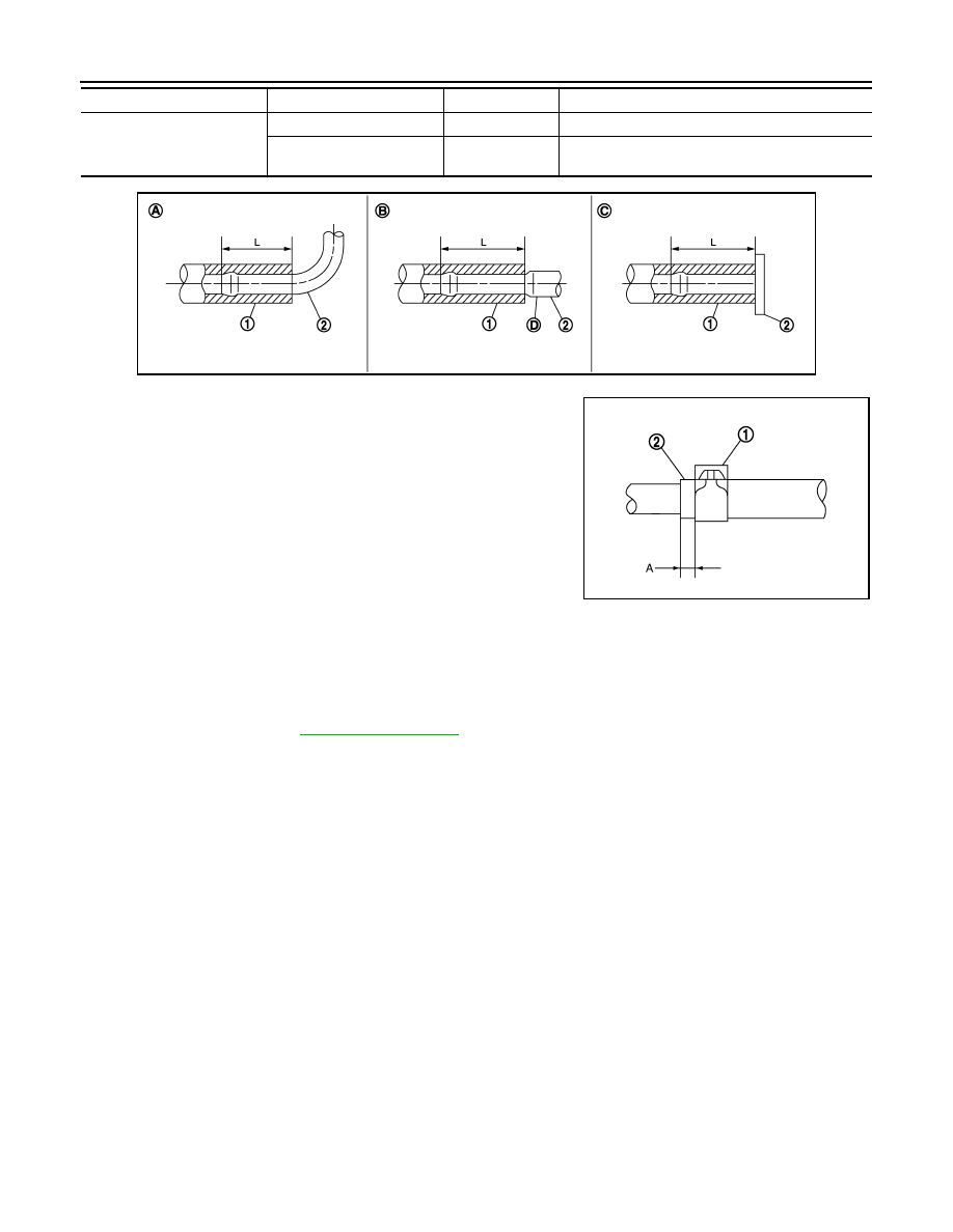
- Insert A/T fluid cooler hoses according to dimension “L” described below.
: Vehicle front
: Bolt
SCIA8269E
Hose name
Hose end
Paint mark
Position of hose clamp
*
A/T fluid cooler hose A
Radiator assembly side
Facing backward
A
A/T fluid cooler tube side
Facing downward
B
A/T fluid cooler hose B
Radiator assembly side
Facing downward
C
A/T fluid cooler tube side
Facing downward
B
D
: Vehicle front
E
: Vehicle upper
JSDIA0795ZZ
(1)
(2)
Tube type
Dimension “L”
A/T fluid cooler hose A
Radiator assembly side
A
End reaches the radius curve end.
A/T fluid cooler tube side
B
30 mm (1.18 in) [End reaches the 2-stage bulge
(D).]
TM-180
< REMOVAL AND INSTALLATION >
[7AT: RE7R01A (VQ35HR)]
FLUID COOLER SYSTEM
- Set hose clamps (1) at the both ends of A/T fluid cooler hoses (2)
with dimension “A” from the hose edge.
- Hose clamp should not interfere with the bulge of fluid cooler tube.
AWD : Inspection and Adjustment
INFOID:0000000005250171
INSPECTION AFTER INSTALLATION
Check A/T fluid leakage.
ADJUSTMENT AFTER INSTALLATION
Adjust A/T fluid level. Refer to
A/T fluid cooler hose B
Radiator assembly side
C
Insert the hose until the hose touches the radiator.
A/T fluid cooler tube side
B
30 mm (1.18 in) [End reaches the 2-stage bulge
(D).]
(1)
(2)
Tube type
Dimension “L”
JSDIA0882ZZ
Dimension “A”
: 5 – 9 mm (0.20 – 0.35 in)
SCIA8123E
TRANSMISSION ASSEMBLY
TM-181
< UNIT REMOVAL AND INSTALLATION >
[7AT: RE7R01A (VQ35HR)]
C
E
F
G
H
I
J
K
L
M
A
B
TM
N
O
P
UNIT REMOVAL AND INSTALLATION
TRANSMISSION ASSEMBLY
2WD
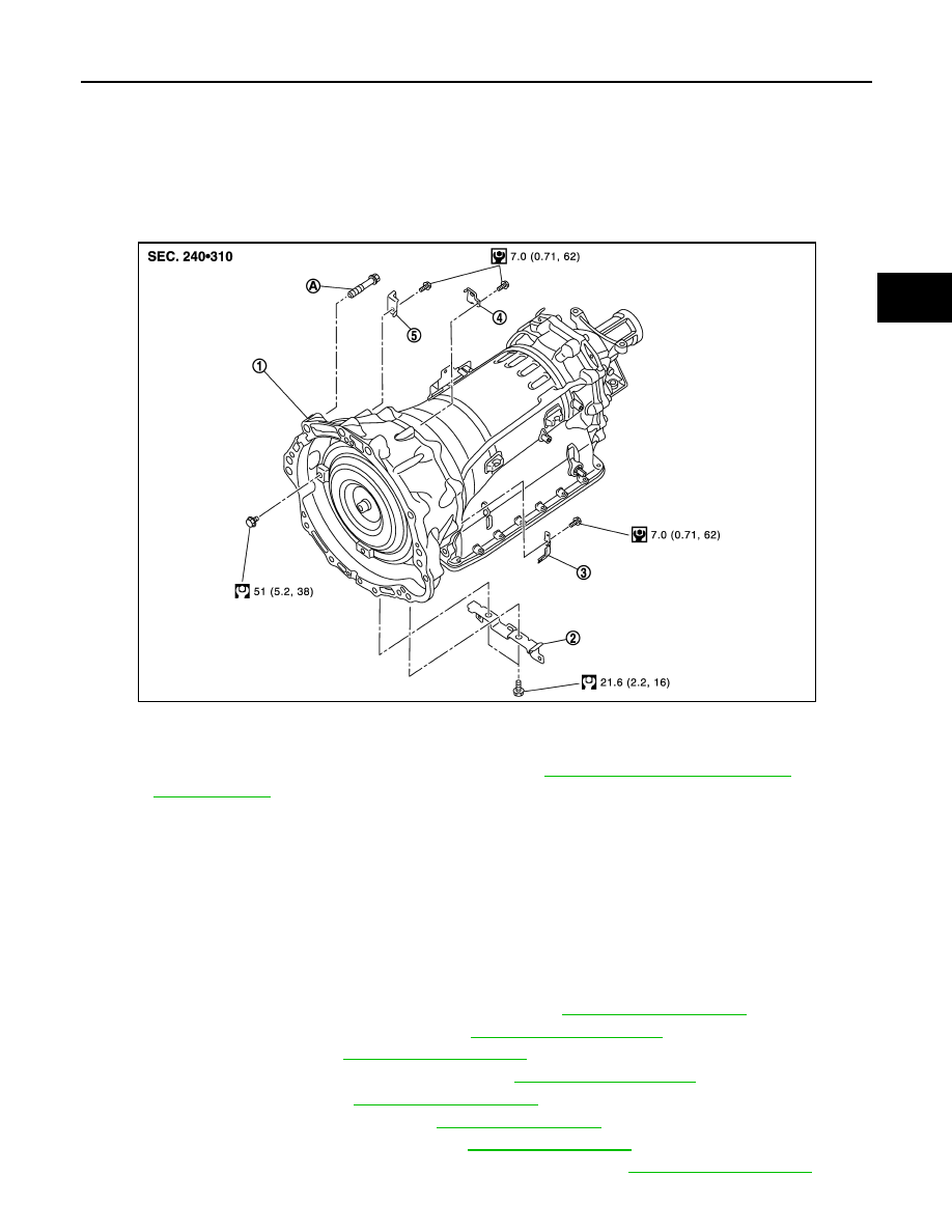
2WD : Exploded View
INFOID:0000000005250172
2WD : Removal and Installation
INFOID:0000000005250173
REMOVAL
CAUTION:
• When removing the A/T assembly from engine, first remove the crankshaft position sensor (POS)
from the A/T assembly.
• Be careful not to damage sensor edge.
1.
Shift the selector lever to “P” position, and then release the parking brake.
2.
Disconnect the battery cable from the negative terminal.
3.
Remove control rod from A/T shift selector assembly. Refer to
4.
Remove propeller shaft assembly (rear). Refer to
.
5.
Remove manual lever. Refer to
.
6.
Remove engine lower cover with a power tool. Refer to
.
7.
Remove front cross bar. Refer to
8.
Remove exhaust mounting bracket. Refer to
9.
Remove three way catalyst (right bank). Refer to
.
10. Remove crankshaft position sensor (POS) from A/T assembly. Refer to
.
1.
A/T assembly
2.
Bracket
3.
Bracket
4.
Bracket
5.
Bracket
A.
Tightening must be done following the installation procedure. Refer to
TM-181, "2WD : Removal and Installation"
JPDIA0850GB

TM-182
< UNIT REMOVAL AND INSTALLATION >
[7AT: RE7R01A (VQ35HR)]
TRANSMISSION ASSEMBLY
CAUTION:
• Never subject it to impact by dropping or hitting it.
• Never disassemble.
• Never allow metal filings, etc. to get on the sensor's front edge magnetic area.
• Never place in an area affected by magnetism.
11. Remove starter motor. Refer to
STR-18, "VQ35HR : Exploded View"
.
12. Remove rear plate cover. Refer to
13. Turn crankshaft, and remove the four tightening bolts for drive plate and torque converter.
CAUTION:
When turning the crankshaft, turn it clockwise as viewed from the front of the engine.
14. Remove A/T fluid cooler tubes from A/T assembly and engine. Refer to
.
15. Plug up openings such as the A/T fluid cooler tube hole.
16. Support A/T assembly with a transmission jack.
CAUTION:
When setting the transmission jack, be careful not to allow it to collide against the drain plug and
overflow plug.
17. Remove rear engine mounting member and engine mounting insulator (rear) with a power tool. Refer to
18. Disconnect A/T assembly connector.
19. Remove harness and brackets.
20. Remove bolts fixing A/T assembly to engine with a power tool.
21. Remove air breather hose. Refer to
.
22. Remove A/T assembly from vehicle.
CAUTION:
• Secure torque converter to prevent it from dropping.
• Secure A/T assembly to a transmission jack.
23. Remove dynamic damper. Refer to
.
INSTALLATION
Note the following, and install in the reverse order of removal.
CAUTION:
Check fitting of dowel pin (
).
SCIA0499E
JPDIA0900ZZ
Нет комментариевНе стесняйтесь поделиться с нами вашим ценным мнением.
Текст