Infiniti FX35, FX50 (S51). Manual — part 861
P1090, P1093 VVEL ACTUATOR MOTOR
EC-985
< DTC/CIRCUIT DIAGNOSIS >
[VK50VE]
C
D
E
F
G
H
I
J
K
L
M
A
EC
N
P
O
P1090, P1093 VVEL ACTUATOR MOTOR
Description
INFOID:0000000005237458
The VVEL actuator motor rotates the control shaft according to the control signal from the VVEL control mod-
ule. The VVEL control module judges whether the VVEL actuator motor controls the angle properly by the
VVEL control shaft position sensor signal.
DTC Logic
INFOID:0000000005237459
DTC DETECTION LOGIC
NOTE:
If DTC P1090 or P1093 is displayed with DTC P1091, first perform the trouble diagnosis for DTC P1091.
Refer to
DTC CONFIRMATION PROCEDURE
1.
PRECONDITIONING
If DTC Confirmation Procedure has been previously conducted, always perform the following procedure
before conducting the next test.
1.
Turn ignition switch OFF and wait at least 10 seconds.
2.
Turn ignition switch ON.
3.
Turn ignition switch OFF and wait at least 10 seconds.
TESTING CONDITION:
Before performing the following procedure, confirm that battery voltage is more than 10 V at idle.
>> GO TO 2.
2.
PERFORM DTC CONFIRMATION PROCEDURE
1.
Start engine and let it idle for 10 second.
2.
Keep the engine speed at approximately 3,500 rpm for at least 10 seconds under no load.
3.
Check DTC.
Is DTC detected?
YES
>> Go to
NO
>> INSPECTION END
Diagnosis Procedure
INFOID:0000000005237460
1.
CHECK GROUND CONNECTION
1.
Turn ignition switch OFF.
2.
Check ground connection M95. Refer to Ground Inspection in
Is the inspection result normal?
YES
>> GO TO 2.
NO
>> Repair or replace ground connection.
2.
VVEL ACTUATOR MOTOR OUTPUT SIGNAL CIRCUIT FOR OPEN AND SHORT
1.
Disconnect VVEL control module harness connector.
2.
Disconnect VVEL actuator motor harness connector.
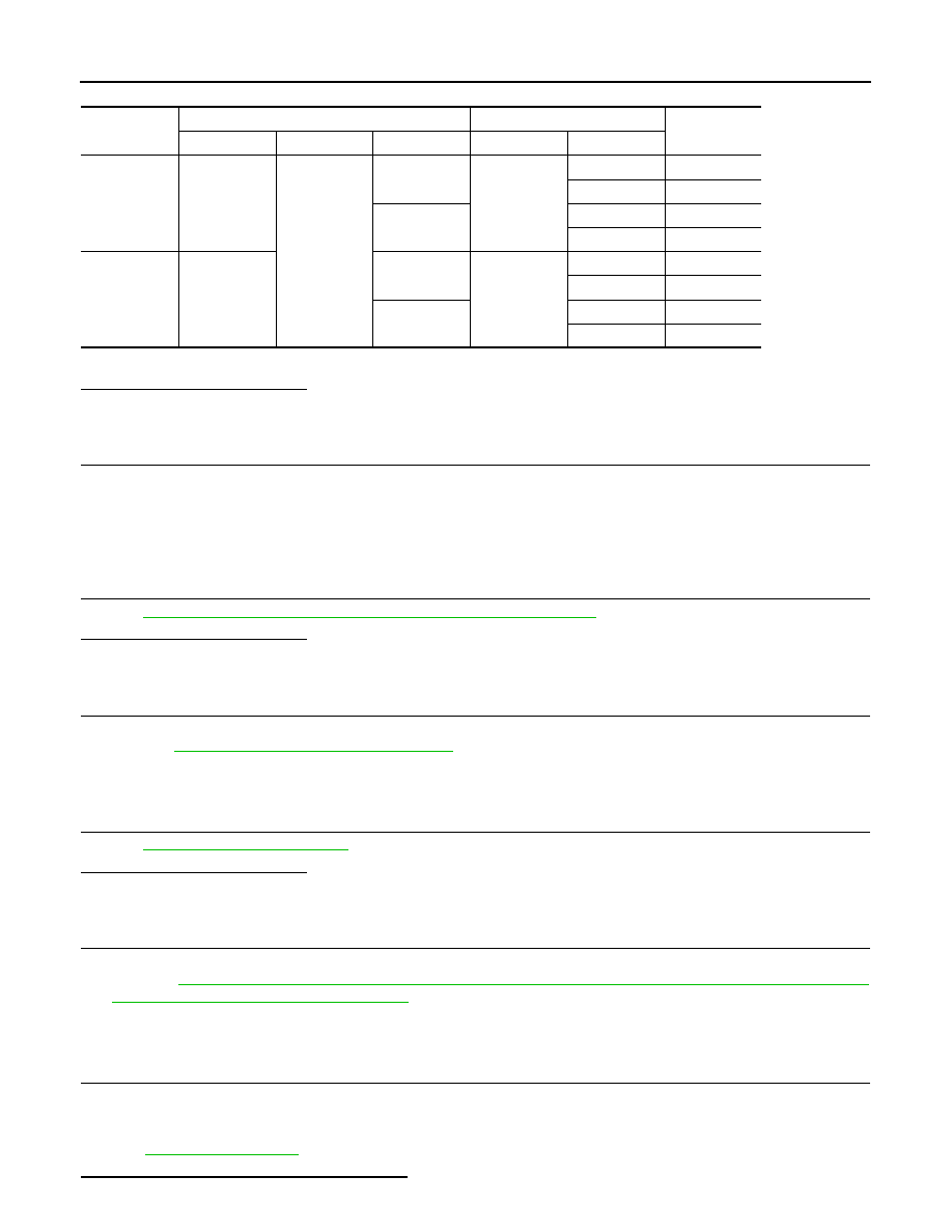
3.
Check the continuity between VVEL control module harness connector and VVEL actuator motor harness
connector.
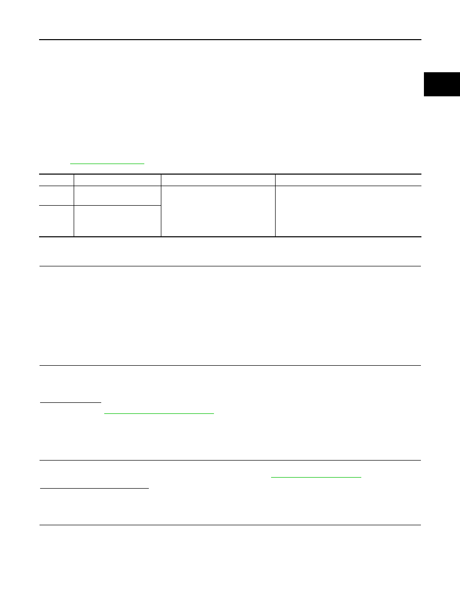
DTC No.
Trouble diagnosis name
DTC detecting condition
Possible cause
P1090
VVEL system performance
(bank 1)
• Event angle difference between the
actual and the target is detected.
• Abnormal current is sent to VVEL
actuator motor.
• Harness or connectors
(VVEL actuator motor circuit is open or shorted.)
• VVEL actuator motor
• VVEL actuator sub assembly
• VVEL ladder assembly
• VVEL control module
P1093
VVEL system performance
(bank 2)
EC-986
< DTC/CIRCUIT DIAGNOSIS >
[VK50VE]
P1090, P1093 VVEL ACTUATOR MOTOR
4.
Also check harness for short to ground and power.
Is the inspection result normal?
YES
>> GO TO 4.
NO
>> GO TO 3.
3.
DETECT MALFUNCTIONING PART
Check the following.
• Harness connectors F10, E10
• Harness for open or short between VVEL actuator motor and VVEL control module
>> Repair open circuit, short to ground or short to power in harness or connectors.
4.
CHECK VVEL ACTUATOR MOTOR
EC-987, "Component Inspection (VVEL ACTUATOR MOTOR)"
.
Is the inspection result normal?
YES
>> GO TO 6.
NO
>> GO TO 5.
5.
REPLACE VVEL ACTUATOR SUB ASSEMBLY
1.
Replace VVEL actuator sub assembly.
2.
EC-988, "Special Repair Requirement"
>> INSPECTION END
6.
CHECK INTERMITTENT INCIDENT
GI-36, "Intermittent Incident"
Is the inspection result normal?
YES
>> GO TO 7.
NO
>> Repair or replace.
7.
REPLACE VVEL CONTROL MODULE
1.
Replace VVEL control module.
2.
Perform
EC-579, "ADDITIONAL SERVICE WHEN REPLACING CONTROL UNIT (VVEL CONTROL
MODULE) : Special Repair Requirement"
.
>> GO TO 8.
8.
PERFORM DTC CONFIRMATION PROCEDURE
1.
Turn ignition switch ON.
2.
Erase DTC.
3.
Perform DTC Confirmation Procedure.
See
Is the DTC P1090 or P1093 displayed again?
DTC No.
VVEL control module
VVEL actuator motor
Continuity
Bank
Connector
Terminal
Connector
Terminal
P1090
1
E16
12
F73
1
Existed
2
Not existed
25
1
Not existed
2
Existed
P1093
2
2
F71
1
Existed
2
Not existed
15
1
Not existed
2
Existed
P1090, P1093 VVEL ACTUATOR MOTOR
EC-987
< DTC/CIRCUIT DIAGNOSIS >
[VK50VE]
C
D
E
F
G
H
I
J
K
L
M
A
EC
N
P
O
YES
>> GO TO 9.
NO >> INSPECTION
END
9.
CHECK VVEL ACTUATOR SUB ASSEMBLY
EC-987, "Component Inspection (VVEL ACTUATOR SUB ASSEMBLY)"
.
Is the inspection result normal?
YES
>> GO TO 11.
NO
>> GO TO 10.
10.
REPLACE VVEL ACTUATOR SUB ASSEMBLY
1.
Replace VVEL actuator sub assembly.
2.
EC-988, "Special Repair Requirement"
>> INSPECTION END
11.
CHECK VVEL LADDER ASSEMBLY
Is the inspection result normal?
YES
>> GO TO 13.
NO
>> GO TO 12.
12.
REPLACE CYLINDER HEAD, VVEL LADDER ASSEMBLY AND VVEL ACTUATOR SUB ASSEMBLY
1.
Replace cylinder head, VVEL ladder assembly and VVEL actuator sub assembly.
2.
EC-988, "Special Repair Requirement"
>> INSPECTION END
13.
CHECK INTERMITTENT INCIDENT
GI-36, "Intermittent Incident"
.
>> INSPECTION END
Component Inspection (VVEL ACTUATOR MOTOR)
INFOID:0000000005237461
1.
CHECK VVEL ACTUATOR MOTOR
1.
Turn ignition switch OFF.
2.
Disconnect VVEL actuator motor harness connector.
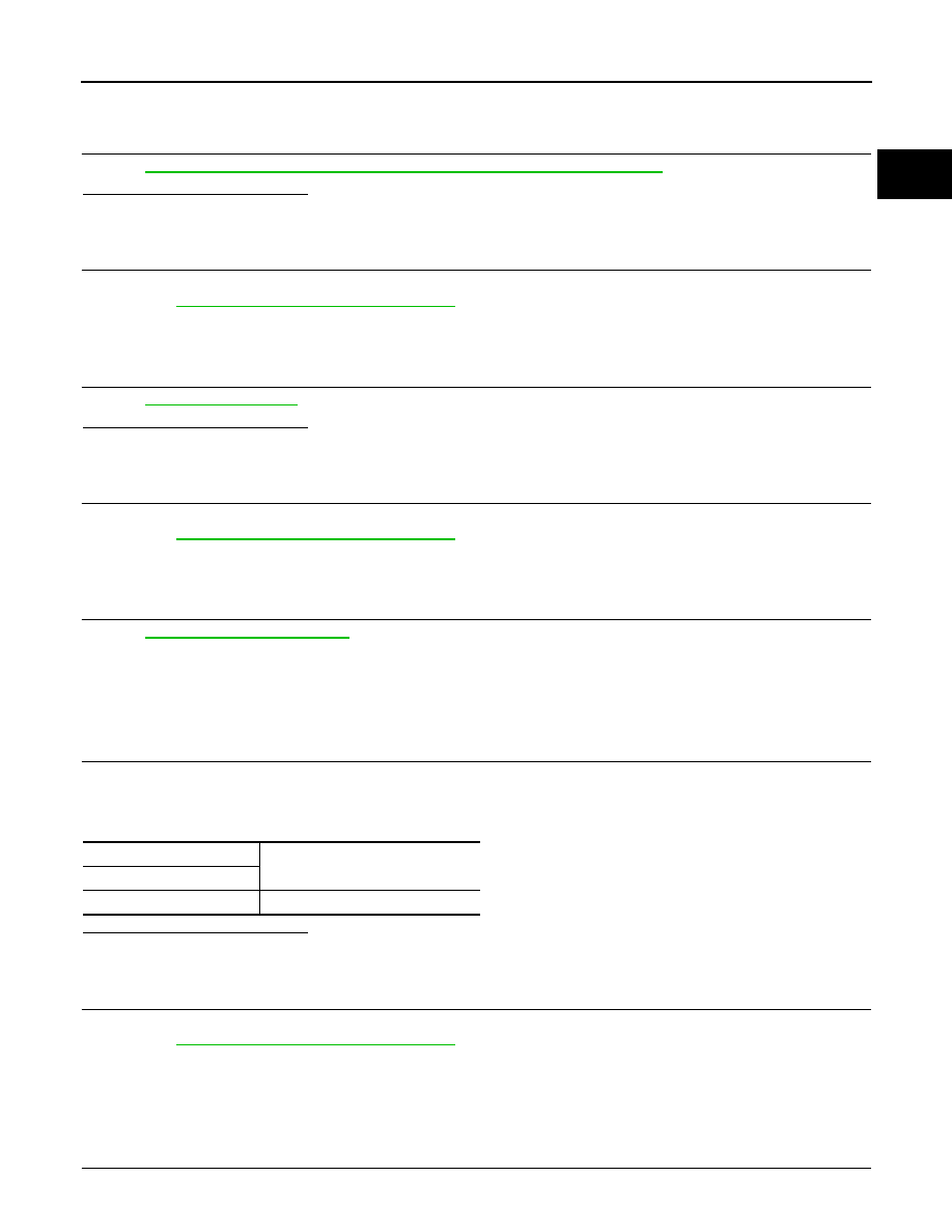
3.
Check resistance between VVEL actuator motor terminals as per the following.
Is the inspection result normal?
YES
>> INSPECTION END
NO
>> GO TO 2.
2.
REPLACE VVEL ACTUATOR SUB ASSEMBLY
1.
Replace VVEL actuator sub assembly.
2.
EC-988, "Special Repair Requirement"
>> INSPECTION END
Component Inspection (VVEL ACTUATOR SUB ASSEMBLY)
INFOID:0000000005237462
1.
CHECK VVEL ACTUATOR SUB ASSEMBLY
1.
Turn ignition switch OFF.
VVEL actuator motor
Resistance
Terminal
1 and 2
16
Ω
or less

EC-988
< DTC/CIRCUIT DIAGNOSIS >
[VK50VE]
P1090, P1093 VVEL ACTUATOR MOTOR
2.
Remove VVEL actuator sub assembly. Refer to
EM-228, "Disassembly and Assembly"
.
3.
Turn the ball screw shaft to check that it works smoothly.
Is the inspection result normal?
YES
>> INSPECTION END
NO
>> GO TO 2.
2.
REPLACE VVEL ACTUATOR SUB ASSEMBLY
1.
Replace VVEL actuator sub assembly.
2.
EC-988, "Special Repair Requirement"
>> INSPECTION END
Special Repair Requirement
INFOID:0000000005237463
1.
PERFORM VVEL CONTROL SHAFT POSITION SENSOR ADJUSTMENT
Refer to
EC-583, "VVEL CONTROL SHAFT POSITION SENSOR ADJUSTMENT : Special Repair Require-
>> GO TO 2.
2.
PERFORM IDLE AIR VOLUME LEARNING
EC-582, "IDLE AIR VOLUME LEARNING : Special Repair Requirement"
>> END
Нет комментариевНе стесняйтесь поделиться с нами вашим ценным мнением.
Текст