Infiniti FX35, FX50 (S51). Manual — part 860
P1089, P1092 VVEL CONTROL SHAFT POSITION SENSOR
EC-981
< DTC/CIRCUIT DIAGNOSIS >
[VK50VE]
C
D
E
F
G
H
I
J
K
L
M
A
EC
N
P
O
P1089, P1092 VVEL CONTROL SHAFT POSITION SENSOR
Description
INFOID:0000000005237454
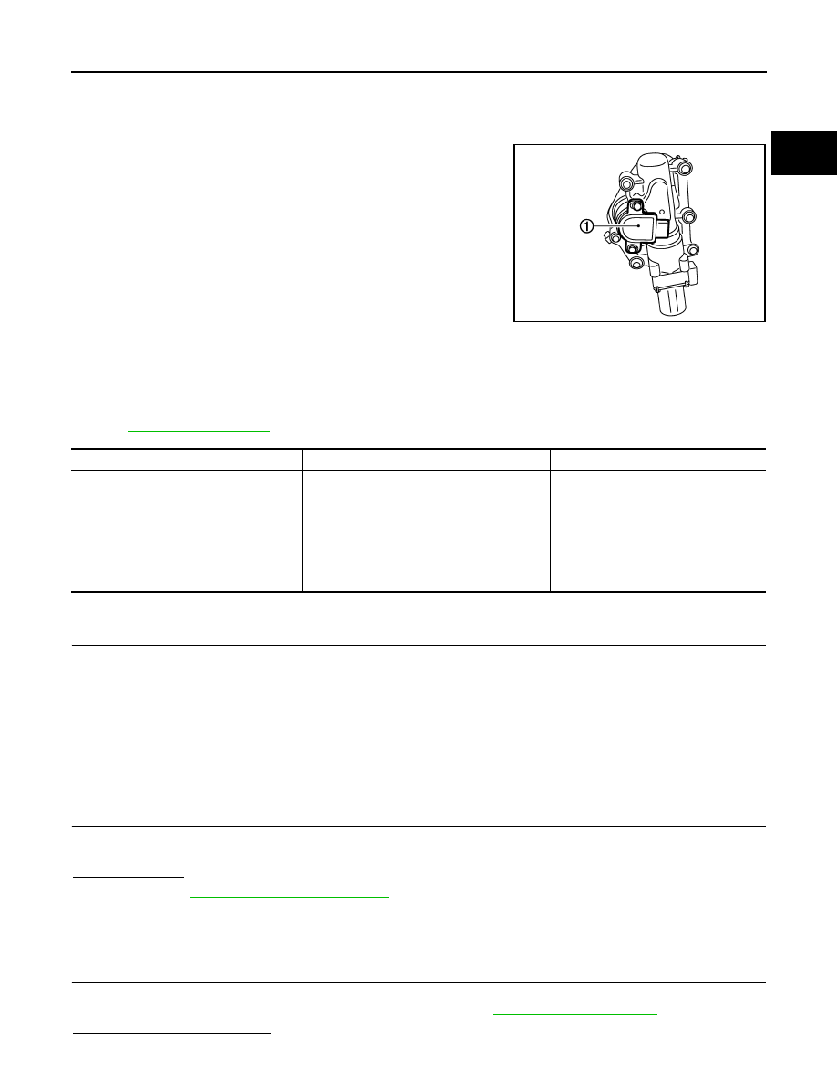
VVEL control shaft position sensor (1) is placed on VVEL actuator
sub assembly and detects the control shaft position angle.
A magnet is pressed into the arm on the edge of control shaft.
The magnetic field changes as the magnet rotates together with the
arm resulting in the output voltage change of the sensor.
VVEL control module detects the actual position angle through the
voltage change and sends the signal to ECM.
DTC Logic
INFOID:0000000005237455
DTC DETECTION LOGIC
NOTE:
If DTC P1089 or P1092 is displayed with DTC P1608, first perform the trouble diagnosis for DTC P1608.
Refer to
.
DTC CONFIRMATION PROCEDURE
1.
PRECONDITIONING
If DTC Confirmation Procedure has been previously conducted, always perform the following procedure
before conducting the next test.
1.
Turn ignition switch OFF and wait at least 10 seconds.
2.
Turn ignition switch ON.
3.
Turn ignition switch OFF and wait at least 10 seconds.
TESTING CONDITION:
Before performing the following procedure, confirm that battery voltage is more than 10 V at idle.
>> GO TO 2.
2.
PERFORM DTC CONFIRMATION PROCEDURE
1.
Start engine and let it idle for 1 second.
2.
Check DTC.
Is DTC detected?
YES
>> Go to
NO
>> INSPECTION END
Diagnosis Procedure
INFOID:0000000005237456
1.
CHECK GROUND CONNECTION
1.
Turn ignition switch OFF.
2.
Check ground connection M95. Refer to Ground Inspection in
Is the inspection result normal?
JMBIA1565ZZ
DTC No.
Trouble diagnosis name
DTC detecting condition
Possible cause
P1089
VVEL control shaft position
sensor (bank 1) circuit
• An excessively low voltage from the sensor
is sent to VVEL control module.
• An excessively high voltage from the sensor
is sent to VVEL control module.
• Rationally incorrect voltage is sent to VVEL
control module compared with the signals
from VVEL control shaft position sensor 1
and VVEL control shaft position sensor 2.
• Harness or connectors
(VVEL control shaft position sensor
circuit is open or shorted.)
• VVEL control shaft position sensor
• VVEL control module
P1092
VVEL control shaft position
sensor (bank 2) circuit
EC-982
< DTC/CIRCUIT DIAGNOSIS >
[VK50VE]
P1089, P1092 VVEL CONTROL SHAFT POSITION SENSOR
YES
>> GO TO 2.
NO
>> Repair or replace ground connection.
2.
VVEL CONTROL SHAFT POSITION SENSOR POWER SUPPLY CIRCUIT
1.
Disconnect VVEL control shaft position sensor harness connector.
2.
Turn ignition switch ON.
3.
Check the voltage between VVEL control shaft position sensor harness connector and ground.
Is the inspection result normal?
YES
>> GO TO 4.
NO
>> GO TO 3.
3.
DETECT MALFUNCTIONING PART
Check the following.
• Harness connectors F10, E10
• Harness for open or short between VVEL control shaft position sensor and VVEL control module
>> Repair open circuit, short to ground or short to power in harness or connectors.
4.
CHECK VVEL CONTROL SHAFT POSITION SENSOR GROUND CIRCUIT FOR OPEN AND SHORT
1.
Turn ignition switch OFF.
2.
Disconnect VVEL control module harness connector.
3.
Check the continuity between VVEL control shaft position sensor harness connector and VVEL control
module harness connector.
4.
Also check harness for short to ground and power.
Is the inspection result normal?
YES
>> GO TO 6.
NO
>> GO TO 5.
5.
DETECT MALFUNCTIONING PART
Check the following.
• Harness connectors F10, E10
• Harness for open or short between VVEL control shaft position sensor and VVEL control module
>> Repair open circuit, short to ground or short to power in harness or connectors.
6.
VVEL CONTROL SHAFT POSITION SENSOR INPUT SIGNAL CIRCUIT FOR OPEN AND SHORT
1.
Check the continuity between VVEL control shaft position sensor harness connector and VVEL control
module harness connector.
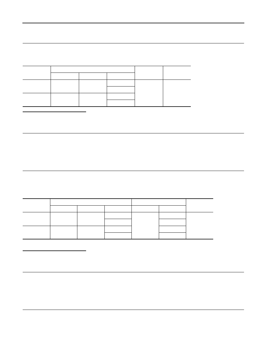
DTC No.
VVEL control shaft position sensor
Ground
Voltage
Bank
Connector
Terminal
P1089
1
F72
3
Ground
Approx. 5V
6
P1092
2
F70
3
6
DTC No.
VVEL control shaft position sensor
VVEL control module
Continuity
Bank
Connector
Terminal
Connector
Terminal
P1089
1
F72
2
E16
9
Existed
5
17
P1092
2
F70
2
4
5
17
P1089, P1092 VVEL CONTROL SHAFT POSITION SENSOR
EC-983
< DTC/CIRCUIT DIAGNOSIS >
[VK50VE]
C
D
E
F
G
H
I
J
K
L
M
A
EC
N
P
O
2.
Also check harness for short to ground and power.
Is the inspection result normal?
YES
>> GO TO 8.
NO
>> GO TO 7.
7.
DETECT MALFUNCTIONING PART
Check the following.
• Harness connectors F10, E10
• Harness for open or short between VVEL control shaft position sensor and VVEL control module
>> Repair open circuit, short to ground or short to power in harness or connectors.
8.
CHECK INTERMITTENT INCIDENT
GI-36, "Intermittent Incident"
.
Is the inspection result normal?
YES
>> GO TO 9.
NO
>> Repair or replace.
9.
REPLACE VVEL CONTROL MODULE
1.
Replace VVEL control module.
2.
Perform
EC-579, "ADDITIONAL SERVICE WHEN REPLACING CONTROL UNIT (VVEL CONTROL
MODULE) : Special Repair Requirement"
.
>> GO TO 10.
10.
PERFORM DTC CONFIRMATION PROCEDURE
1.
Turn ignition switch ON.
2.
Erase DTC.
3.
Perform DTC Confirmation Procedure.
See
.
Is the DTC P1089 or P1092 displayed again?
YES
>> GO TO 11.
NO
>> INSPECTION END
11.
REPLACE VVEL ACTUATOR SUB ASSEMBLY
1.
Replace VVEL actuator sub assembly.
2.
EC-983, "Special Repair Requirement"
>> INSPECTION END
Special Repair Requirement
INFOID:0000000005237457
1.
PERFORM VVEL CONTROL SHAFT POSITION SENSOR ADJUSTMENT
EC-583, "VVEL CONTROL SHAFT POSITION SENSOR ADJUSTMENT : Special Repair Require-
>> GO TO 2.
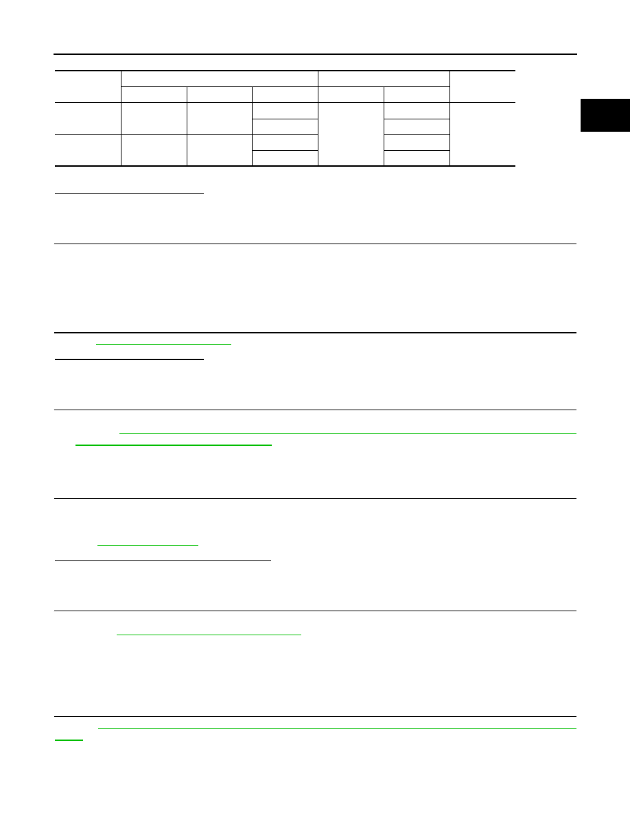
DTC No.
VVEL control shaft position sensor
VVEL control module
Continuity
Bank
Connector
Terminal
Connector
Terminal
P1089
1
F72
1
E16
3
Existed
4
16
P1092
2
F70
1
5
4
18
EC-984
< DTC/CIRCUIT DIAGNOSIS >
[VK50VE]
P1089, P1092 VVEL CONTROL SHAFT POSITION SENSOR
2.
PERFORM IDLE AIR VOLUME LEARNING
EC-582, "IDLE AIR VOLUME LEARNING : Special Repair Requirement"
>> END
Нет комментариевНе стесняйтесь поделиться с нами вашим ценным мнением.
Текст