Infiniti FX35, FX50 (S51). Manual — part 1217
INL-68
< DTC/CIRCUIT DIAGNOSIS >
DOOR SWITCH CIRCUIT
2.
Disconnect the total illumination control unit connector.
3.
Turn ignition switch ON.
4.
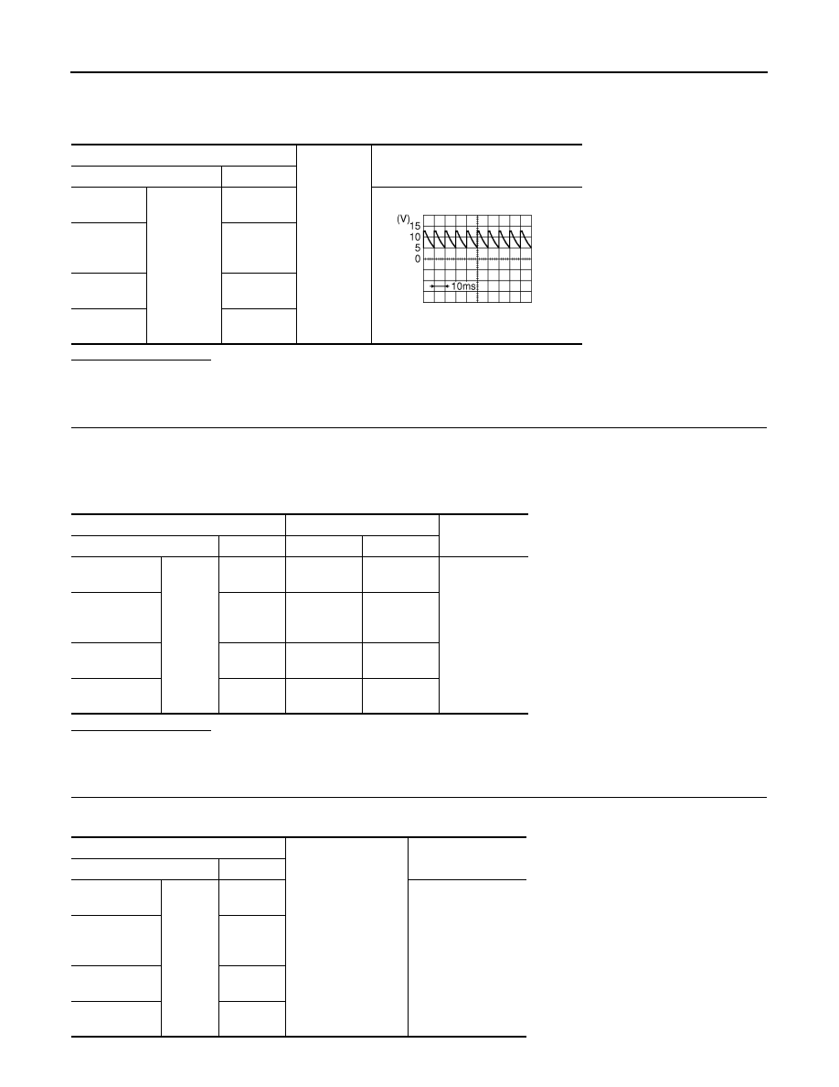
Check voltage between the total illumination control unit harness connector and ground.
Does continuity exist?
YES
>> Replace the total illumination control unit.
NO
>> GO TO3.
3.
CHECK EACH DOOR SWITCH SIGNAL CIRCUIT FOR OPEN
1.
Turn ignition switch OFF.
2.
Disconnect each door switch connector.
3.
Check continuity between the total illumination control unit harness connector and each door switch har-
ness connector.
Does continuity exist?
YES
>> GO TO 4.
NO
>> Repair the harnesses or connectors.
4.
CHECK EACH DOOR SWITCH SIGNAL CIRCUIT FOR SHORT
Check continuity between total illumination control unit harness connector and ground.
Total illumination control unit
Ground
Voltage (Approx.)
Connector
Terminal
Front door
(driver side)
M129
29
8.5 - 9.0 V
Front door
(passenger
side)
8
Rear door
(LH)
9
Rear door
(RH)
25
JPMIA0594GB
Total illumination control unit
Door switch
Continuity
Connector
Terminal
Connector
Terminal
Front door
(driver side)
M129
29
B16
2
Existed
Front door
(passenger
side)
8
B216
2
Rear door
(LH)
9
B23
2
Rear door
(RH)
25
B223
2
Total illumination control unit
Ground
Continuity
Connector
Terminal
Front door
(driver side)
M129
29
Not existed
Front door
(passenger
side)
8
Rear door
(LH)
9
Rear door
(RH)
25
DOOR SWITCH CIRCUIT
INL-69
< DTC/CIRCUIT DIAGNOSIS >
C
D
E
F
G
H
I
J
K
M
A
B
INL
N
O
P
Does continuity exist?
YES
>> Repair the harnesses or connectors.
NO
>> Check each door switch. Refer to
INL-70
< DTC/CIRCUIT DIAGNOSIS >
ROOM LAMP REQUEST SIGNAL CIRCUIT
ROOM LAMP REQUEST SIGNAL CIRCUIT
Component Function Check
INFOID:0000000005245610
1.
CHECK ROOM LAMP TIMER SETTING
CONSULT-III WORK SUPPORT
1.
Select “SET I/L D-UNLCK INTCON” of BCM (INT LAMP) work support item.
2.
Check the setting status.
Is the setting “On”?
YES
>> GO TO 2.
NO
>> Change the setting to “On”
2.
CHECK ROOM LAMP TIMER SIGNAL BY CONSULT-III
CONSULT-III DATA MONITOR
1.
Turn ignition switch OFF.
2.
Select “ROOM LAMP REQ” of TOTAL ILLUM C/U data monitor item.
3.
While operating the door lock/door unlock, check the monitor status.
Is the item status normal?
YES
>> Room lamp timer signal circuit is normal.
NO
>> Refer to
.
Diagnosis Procedure
INFOID:0000000005245611
1.
CHECK ROOM LAMP TIMER SIGNAL INPUT
CONSULT-III ACTIVE TEST
1.
Turn ignition switch ON.
2.
Select “INT LAMP” of BCM (INT LAMP) active test item.
3.
While operating the test items, check voltage between total illumination control unit harness connector
and ground.
Is the measurement value normal?
YES
>> Replace the total illumination control unit.
NO
>> GO TO 2.
2.
CHECK ROOM LAMP TIMER SIGNAL CIRCUIT FOR OPEN
1.
Turn ignition switch OFF.
2.
Disconnect the total illumination control unit and BCM connectors.
3.
Check continuity between the total illumination control unit harness connector and BCM harness connec-
tor.
Work support item
Setting status
SET I/L D-UNLCK INTCON
On
Monitor item
Condition
Monitor status
ROOM LAMP REQ
Door is unlocked
On
Door is locked
Off
Total illumination control
unit
Ground
Test item
Voltage
(Approx.)
Connector
Terminal
INT LAMP
M129
28
On
5 V
Off
0 V
ROOM LAMP REQUEST SIGNAL CIRCUIT
INL-71
< DTC/CIRCUIT DIAGNOSIS >
C
D
E
F
G
H
I
J
K
M
A
B
INL
N
O
P
Does continuity exist?
YES
>> GO TO 3.
NO
>> Repair the harnesses or connectors.
3.
CHECK ROOM LAMP TIMER SIGNAL FOR SHORT
Check continuity between the total illumination control unit harness connector and ground.
Does continuity exist?
YES
>> Repair the harnesses or connectors.
NO
>> Replace the BCM.
Diagnosis Procedure
INFOID:0000000005245612
Total illumination control unit
BCM
Continuity
Connector
Terminal
Connector
Terminal
M129
28
M119
19
Existed
Total illumination control unit
Ground
Continuity
Connector
Terminal
M129
28
Not existed
Нет комментариевНе стесняйтесь поделиться с нами вашим ценным мнением.
Текст