Infiniti FX35, FX50 (S51). Manual — part 1580
RSU-18
< REMOVAL AND INSTALLATION >
REAR STABILIZER
REAR STABILIZER
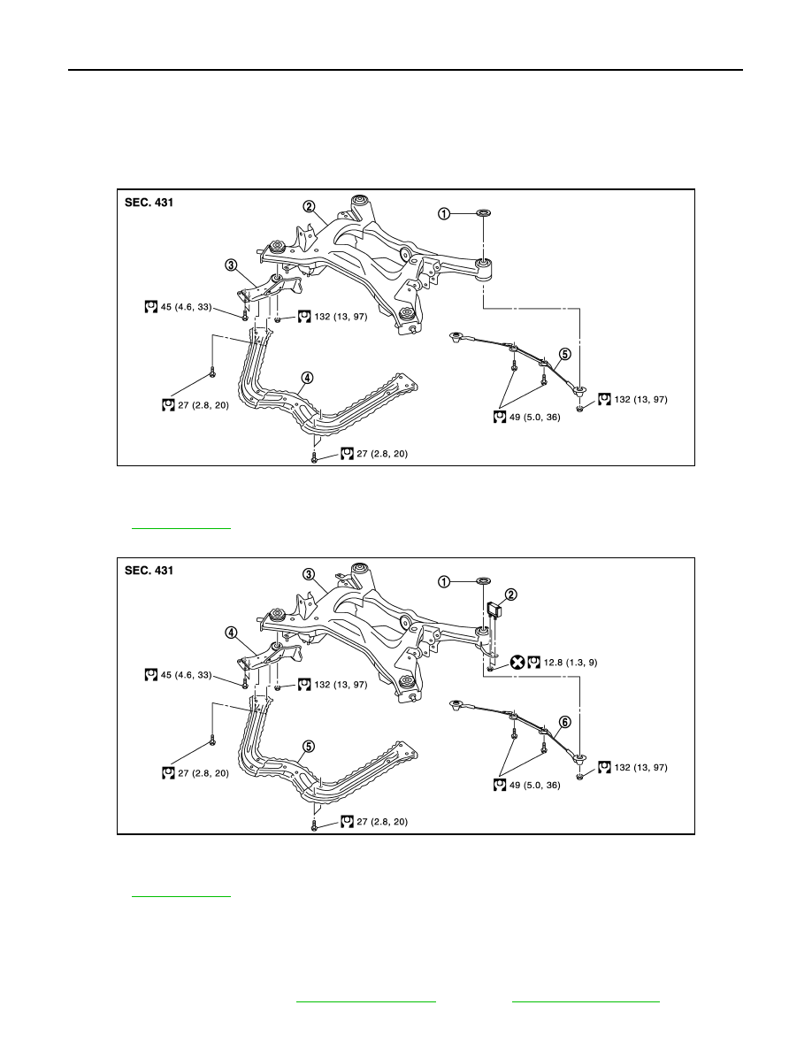
Exploded View
INFOID:0000000005249868
STABILIZER CLAMP FIXING METHOD : NUT
STABILIZER CLAMP FIXING METHOD : BOLT
Removal and Installation
INFOID:0000000005249869
REMOVAL
1.
Suspension arm
2.
Stabilizer connecting rod mounting
bracket
3.
Stabilizer connecting rod
4.
Stabilizer bar
5.
Stabilizer bushing
6.
Stabilizer clamp
Refer to
for symbols in the figure.
JPEIB0117GB
1.
Suspension arm
2.
Stabilizer connecting rod mounting
bracket
3.
Stabilizer connecting rod
4.
Stabilizer bar
5.
Stabilizer bushing
6.
Stabilizer clamp
Refer to
for symbols in the figure.
JPEIB0181GB
REAR STABILIZER
RSU-19
< REMOVAL AND INSTALLATION >
C
D
F
G
H
I
J
K
L
M
A
B
RSU
N
O
P
1.
Remove center muffler. Refer to
(VK50VE).
2.
Remove under cover.
3.
Remove stabilizer connecting rod mounting nuts (lower side) with power tool, and remove stabilizer con-
necting rod from stabilizer bar.
4.
Remove stabilizer connecting rod mounting nuts (upper side) with power tool, and remove stabilizer con-
necting rod from stabilizer connecting rod mounting bracket.
5.
Remove mounting bolts or nuts on stabilizer clamp with power tool, and remove stabilizer bar.
6.
Remove stabilizer connecting rod mounting bracket.
INSTALLATION
Note the following, and install in the reverse order of removal.
• Tighten the mounting nut to the specified torque while holding a hexagonal part of stabilizer connecting rod
side.
Inspection
INFOID:0000000005249870
INSPECTION AFTER REMOVAL
Check stabilizer bar, stabilizer connecting rod, stabilizer bushing and stabilizer clamp for deformation, cracks
or damage. Replace it if necessary.
RSU-20
< UNIT REMOVAL AND INSTALLATION >
REAR SUSPENSION MEMBER
UNIT REMOVAL AND INSTALLATION
REAR SUSPENSION MEMBER
Exploded View
INFOID:0000000005249871
VQ35HR
VK50VE
Removal and Installation
INFOID:0000000005249872
REMOVAL
1.
Remove tires with power tool.
2.
Remove center muffler. Refer to
(VK50VE).
JPEIB0118GB
1.
Mount stopper
2.
Rear suspension member
3.
Rear suspension member stay
4.
Tunnel stay
5.
Pin stay
Refer to
for symbols in the figure.
JPEIB0194GB
1.
Mount stopper
2.
Dynamic damper
3.
Rear suspension member
4.
Rear suspension member stay
5.
Tunnel stay
6.
Pin stay
Refer to
for symbols in the figure.

REAR SUSPENSION MEMBER
RSU-21
< UNIT REMOVAL AND INSTALLATION >
C
D
F
G
H
I
J
K
L
M
A
B
RSU
N
O
P
3.
Remove radius rod. Refer to
4.
Remove caliper assembly. Hang caliper assembly in a place where it will not interfere with work. Refer to
BR-56, "BRAKE CALIPER ASSEMBLY (1 PISTON TYPE) : Exploded View"
"BRAKE CALIPER ASSEMBLY (2 PISTON TYPE) : Exploded View"
CAUTION:
Avoid depressing brake pedal while brake caliper is removed.
5.
Remove disc rotor. Refer to
BR-57, "BRAKE CALIPER ASSEMBLY (1 PISTON TYPE) : Removal and
(1 piston type),
BR-61, "BRAKE CALIPER ASSEMBLY (2 PISTON TYPE) : Removal and
(2 piston type).
6.
Remove wheel sensor harness from rear suspension member. Refer to
.
7.
Remove height sensor harness from rear suspension member (with xenon head lamp). Refer to
8.
Remove shock absorber actuator harness connector (with Continuous Damping Control).
9.
Remove stabilizer bar. Refer to
10. Remove drive shaft. Refer to
.
11. Remove propeller shaft. Refer to
(3F80AR-1VL107),
(3F-R-2VL107).
12. Remove final drive. Refer to
DLN-207, "2WD : Exploded View"
[R200 (AWD)],
13. Remove parking brake cable mounting bolt and separate parking brake cable from vehicle and rear sus-
pension member. Refer to
.
14. Remove shock absorber mounting bolts (lower side). Refer to
.
15. Remove rear lower link and coil spring. Refer to
16. Remove RAS actuator assembly (with RAS). Refer to
.
17. Set suitable jack under rear suspension member.
18. Remove pin stay.
19. Remove dynamic dampers. (VK50VE)
20. Remove tunnel stay.
21. Remove rear suspension member stay.
22. Slowly lower jack, then remove rear suspension member, suspension arm, front lower link, wheel hub and
housing from vehicle as a unit.
23. Remove mounting bolts and nuts, then remove suspension arm, front lower link, wheel hub and housing
from rear suspension member. Refer to
,
INSTALLATION
Note the following, and install in the reverse order of the removal.
• Perform the final tightening of each of parts under unladen conditions, which were removed when removing
rear suspension assembly.
• Check wheel sensor harness for proper connection. Refer to
.
• Never reuse cotter pin.
Inspection
INFOID:0000000005249873
INSPECTION AFTER REMOVAL
Check rear suspension member for deformation, cracks, or any other damage. Replace if necessary.
INSPECTION AFTER INSTALLATION
1.
Check shock absorber actuator harness connector for proper connection (with Continuous Damping Con-
trol).
2.
Adjust parking brake operation (stroke). Refer to
PB-3, "Inspection and Adjustment"
3.
Check wheel alignment. Refer to
Нет комментариевНе стесняйтесь поделиться с нами вашим ценным мнением.
Текст