Infiniti FX35, FX50 (S51). Manual — part 978
EM-212
< UNIT DISASSEMBLY AND ASSEMBLY >
[VK50VE]
TIMING CHAIN
TIMING CHAIN
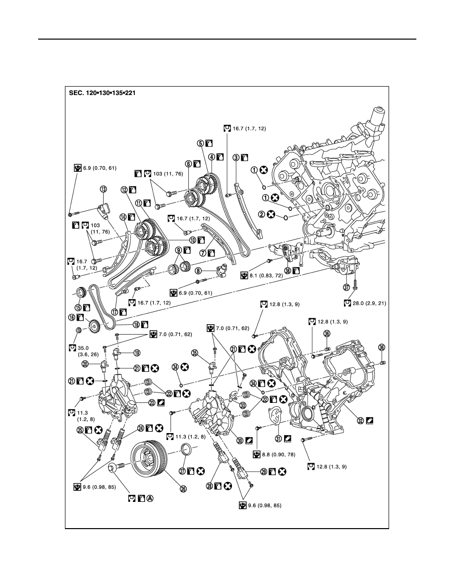
Exploded View
INFOID:0000000005245250
1.
O-ring
2.
O-ring
3.
Tension guide (bank 2)
4.
Timing chain (bank 2)
5.
Camshaft sprocket (INT) (bank 2)
6.
Camshaft sprocket (EXH) (bank 2)
7.
Slack guide (bank 2)
8.
Timing chain tensioner (bank 2)
9.
Crankshaft sprocket
JPBIA2120GB
TIMING CHAIN
EM-213
< UNIT DISASSEMBLY AND ASSEMBLY >
[VK50VE]
C
D
E
F
G
H
I
J
K
L
M
A
EM
N
P
O
Disassembly and Assembly
INFOID:0000000005245251
DISASSEMBLY
1.
Remove auto tensioners and idler pulley. Refer to
.
2.
Remove oil level gauge and oil level gauge guide. Refer to
.
3.
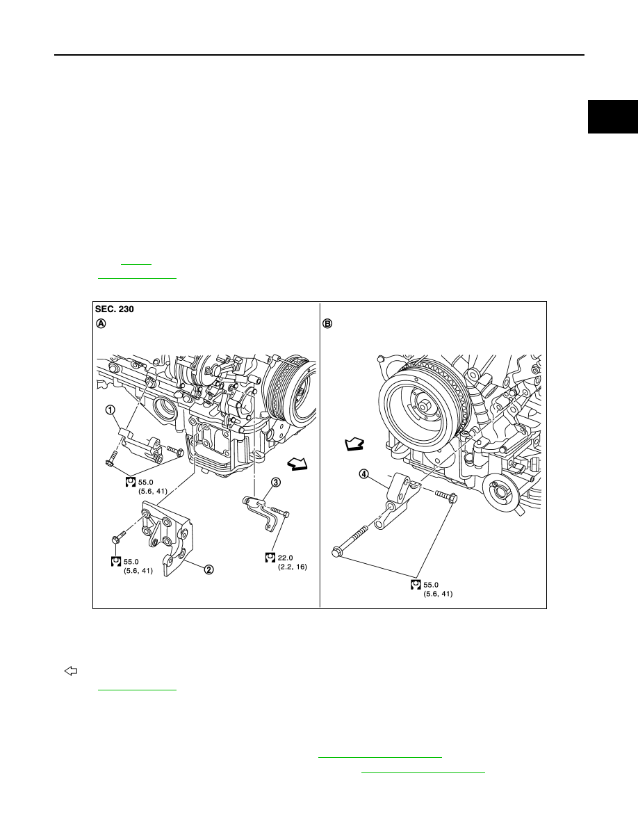
Remove alternator bracket and alternator stay.
10.
Camshaft sprocket (EXH) (bank 1)
11. Timing chain (bank 1)
12.
Camshaft sprocket (INT) (bank 1)
13.
Timing chain tensioner (bank 1)
14. Slack guide (bank 1)
15.
Oil pump sprocket (crankshaft side)
16.
Oil pump sprocket (oil pump side)
17. Tension guide (bank 1)
18.
Oil pump drive chain
19.
Camshaft position sensor (INT)
(bank 2)
20.
Camshaft position sensor (EXH)
(bank 2)
21.
O-ring
22.
Seal ring
23. Valve timing control cover (bank 2)
24.
Intake valve timing control solenoid valve
(bank 2)
25.
Exhaust valve timing control sole-
noid valve (bank 2)
26. Crankshaft pulley
27.
Front oil seal
28.
Intake valve timing control solenoid
valve (bank 1)
29.
Exhaust valve timing control sole-
noid valve (bank 1)
30.
Valve timing control cover (bank 1)
31.
Timing chain tensioner cover
32. Front cover
33.
Camshaft position sensor (EXH) (bank 1)
34.
O-ring
35.
Camshaft position sensor (INT)
(bank 1)
36.
Oil filter (for valve timing control solenoid
valve)
37.
Oil pump
38. Oil pump drive chain tensioner
A.
Refer to
for symbol marks in the figure.
1.
Alternator bracket
2.
Power steering pump bracket
3.
Alternator support
4.
A/C compressor bracket
A.
Right side
B.
Front side
: Engine front
for symbol marks in the figure.
JPBIA2296GB
EM-214
< UNIT DISASSEMBLY AND ASSEMBLY >
[VK50VE]
TIMING CHAIN
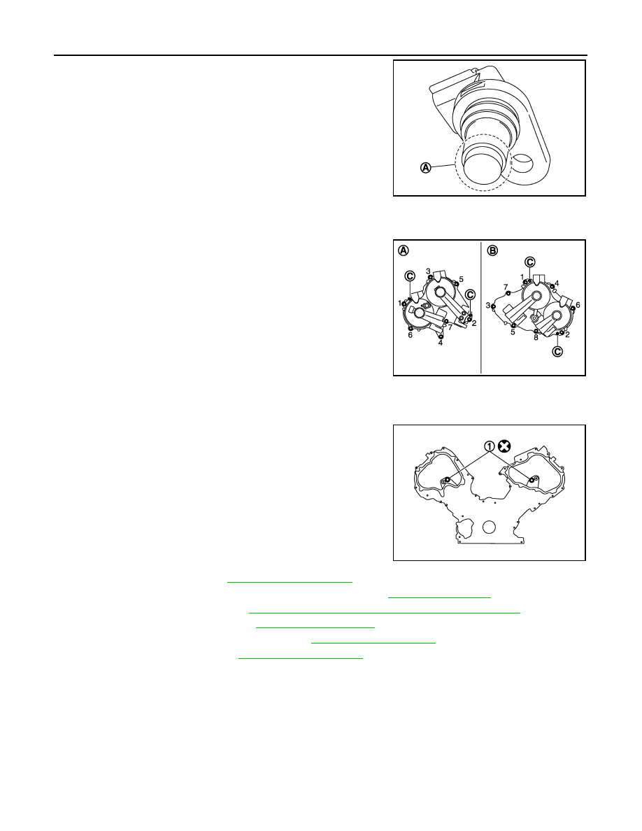
4.
Remove camshaft position sensors.
CAUTION:
• Handle carefully to avoid dropping and shocks.
• Never disassemble.
• Never allow metal powder to adhere to magnetic part at
sensor tip.
• Never place sensors in a location where they are exposed
to magnetism.
5.
Remove valve timing control cover as per the following:
a.
Disconnect valve timing control solenoid valve harness connector.
b.
Loosen mounting bolts in the reverse order as shown in the fig-
ure.
CAUTION:
• Exercise care not to damage mating surfaces.
• Shaft is internally jointed with camshaft sprocket center
hole. When removing, keep it horizontal until it is com-
pletely disconnected.
6.
Remove valve timing control solenoid valve (INT and EXH), if necessary.
CAUTION:
Valve timing control solenoid valve is not reusable. Never remove it unless required.
7.
Remove O-rings (1) from front cover.
8.
Remove rocker cover. Refer to
9.
Obtain No. 1 cylinder at TDC of its compression stroke. Refer to
10. Remove crankshaft pulley. Refer to
EM-194, "FRONT OIL SEAL : Removal and Installation"
.
11. Remove water pump pulley. Refer to
12. Remove oil pan (lower) and oil strainer. Refer to
13. Remove oil pan (upper). Refer to
.
14. Remove front cover as per the following:
A
: Keep free from magnetic materials
JPBIA0454ZZ
A
: Bank 2
B
: Bank 1
C
: Dowel pin hole
JPBIA2118ZZ
JPBIA2117ZZ
TIMING CHAIN
EM-215
< UNIT DISASSEMBLY AND ASSEMBLY >
[VK50VE]
C
D
E
F
G
H
I
J
K
L
M
A
EM
N
P
O
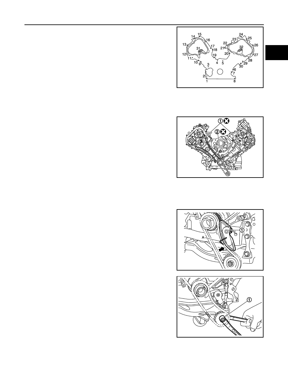
a.
Loosen mounting bolts in reverse order as shown in the figure.
b.
Insert a suitable tool into the notch at front cover.
• Pry off case by moving a suitable tool.
CAUTION:
• Exercise care not to damage mating surfaces.
• After removal, handle front cover carefully so it does not
tilt, cant, or warp under a load.
15. Remove front oil seal from front cover using suitable tool.
• Use screwdriver for removal.
CAUTION:
Be careful not to damage front cover.
16. Remove O-rings (1), (2) from cylinder heads and cylinder block.
17. Remove oil filter (for valve timing control solenoid valve), if necessary.
18. Remove timing chain tensioner cover from front cover, if necessary.
• Use seal cutter [SST: KV10111100 (J-37228)] to cut liquid gasket for removal.
19. Remove oil pump drive chain as per the following:
a.
Push oil pump drive chain tensioner (1).
b.
Insert a stopper pin (A) into the body hole.
c.
Hold the two flat parts of oil pump shaft, and then loosen the oil
pump sprocket (oil pump side) nut.
CAUTION:
Secure the oil pump unit shaft with the two flat parts.
20. Remove oil pump drive chain tensioner.
21. Remove timing chain tensioner (bank 1) as per the following:
JPBIA2116ZZ
JPBIA2115ZZ
JPBIA2303ZZ
1
: Oil pump sprocket (oil pump side)
JPBIA2298ZZ
Нет комментариевНе стесняйтесь поделиться с нами вашим ценным мнением.
Текст