Infiniti FX35, FX50 (S51). Manual — part 977
EM-208
< UNIT DISASSEMBLY AND ASSEMBLY >
[VK50VE]
OIL PAN (UPPER)
OIL PAN (UPPER)
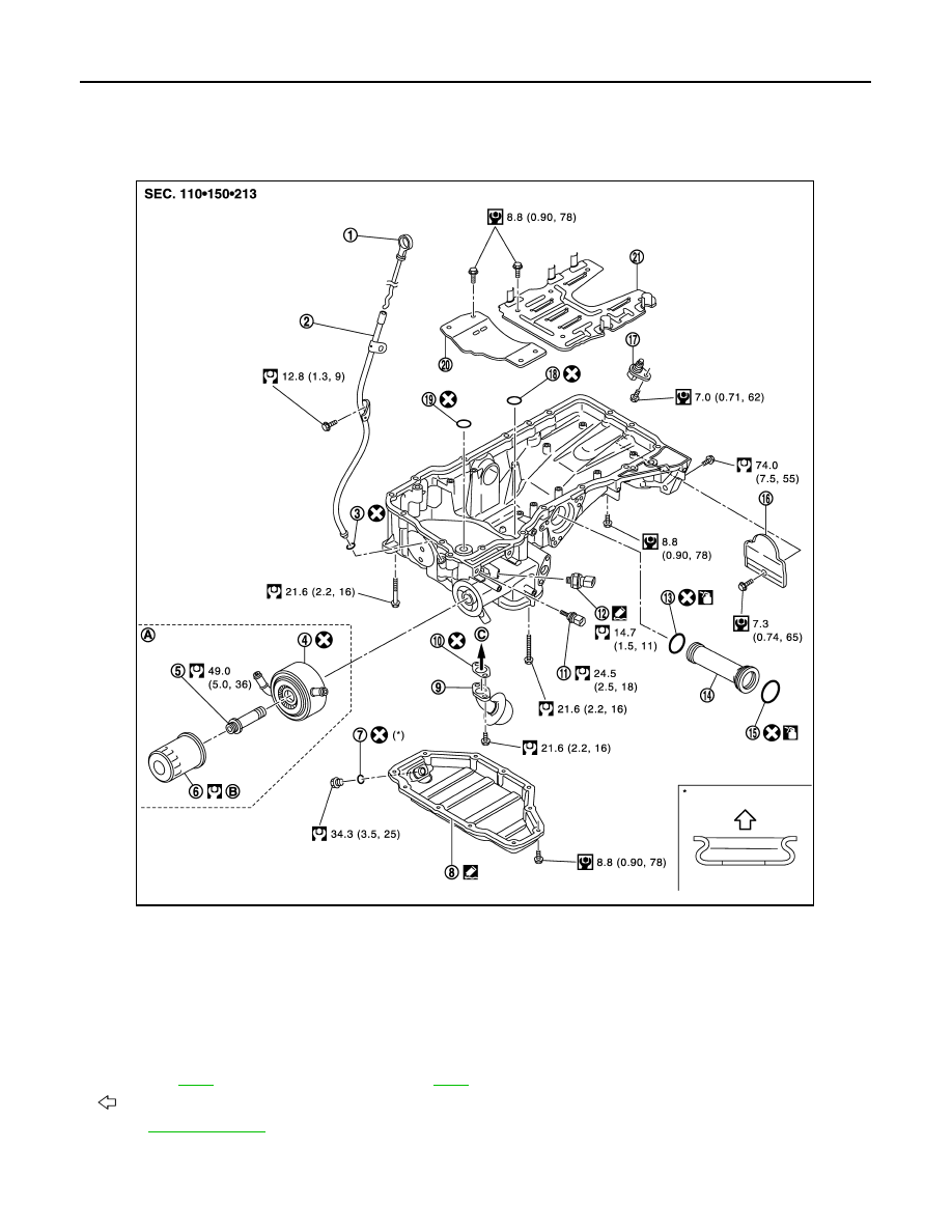
Exploded View
INFOID:0000000005245247
1.
Oil level gauge
2.
Oil level gauge guide
3.
O-ring
4.
Oil cooler
5.
Connector bolt
6.
Oil filter
7.
Drain plug washer
8.
Oil pan (lower)
9.
Oil strainer
10. Gasket
11.
Oil temperature sensor
12. Oil pressure switch
13. O-ring
14. Axle pipe
15. O-ring
16. Rear plate cover
17. Crankshaft position sensor (POS)
18. O-ring
19. O-ring
20. Baffle plate
21. Baffle plate
A.
Refer to
B.
Refer to
C.
Oil pump side
: Oil pan side
for symbols in the figure.
JPBIA2088GB
OIL PAN (UPPER)
EM-209
< UNIT DISASSEMBLY AND ASSEMBLY >
[VK50VE]
C
D
E
F
G
H
I
J
K
L
M
A
EM
N
P
O
Disassembly and Assembly
INFOID:0000000005245248
DISASSEMBLY
WARNING:
To avoid the danger of being scalded, never drain engine oil when engine is hot.
1.
Remove oil filter. Refer to
LU-28, "Removal and Installation"
2.
Remove oil cooler. Refer to
3.
Remove A/C compressor and A/C compressor bracket. Refer to
4.
Remove oil level gauge and oil level gauge guide.
5.
Remove oil pressure switch and oil temperature sensor if necessary.
6.
Remove rear plate cover.
7.
Remove oil pan (lower). Refer to
.
8.
Remove oil strainer. Refer to
9.
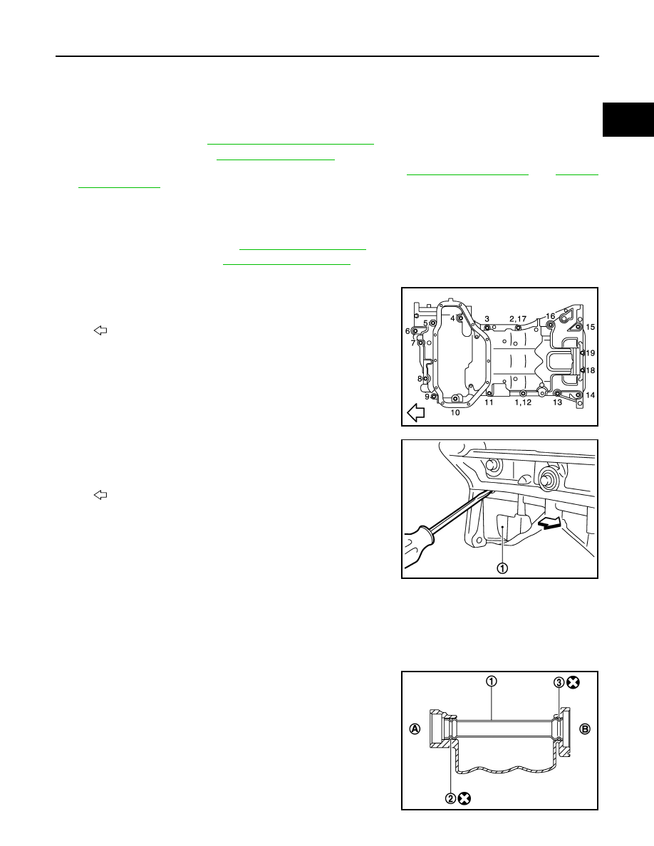
Remove oil pan (upper) as per the following:
a.
Loosen mounting bolts in the reverse order as shown in the fig-
ure with power tool to remove.
NOTE:
Disregard No. 12, 17 when loosening.
b.
Insert a suitable tool into the notch at oil pan (upper) (1) as
shown.
• Pry off case by moving a suitable tool.
CAUTION:
Be careful not to damage the mating surfaces.
10. Remove O-ring from bottom of cylinder block and oil pump.
11. Remove baffle plate, if necessary.
12. Remove axle pipe from oil pan (upper), if necessary.
• Pull axle pipe from oil pan (upper) using a suitable drift.
ASSEMBLY
1.
Install axle pipe (1) to oil pan (upper), if removed.
• Lubricate O-ring groove of axle pipe, O-ring, and O-ring joint of
oil pan with new engine oil.
• Install axle pipe to oil pan (upper) from drive shaft (LH) side.
CAUTION:
Insert it with care to prevent O-ring from sliding.
: Engine front
JPBIA2089ZZ
: Engine front
JPBIA2299ZZ
2
: O-ring
3
: O-ring (with identification paint)
A
: Front final drive side
B
: Drive shaft (LH) side
JPBIA2122ZZ
EM-210
< UNIT DISASSEMBLY AND ASSEMBLY >
[VK50VE]
OIL PAN (UPPER)
2.
Install oil pan (upper) as per the following:
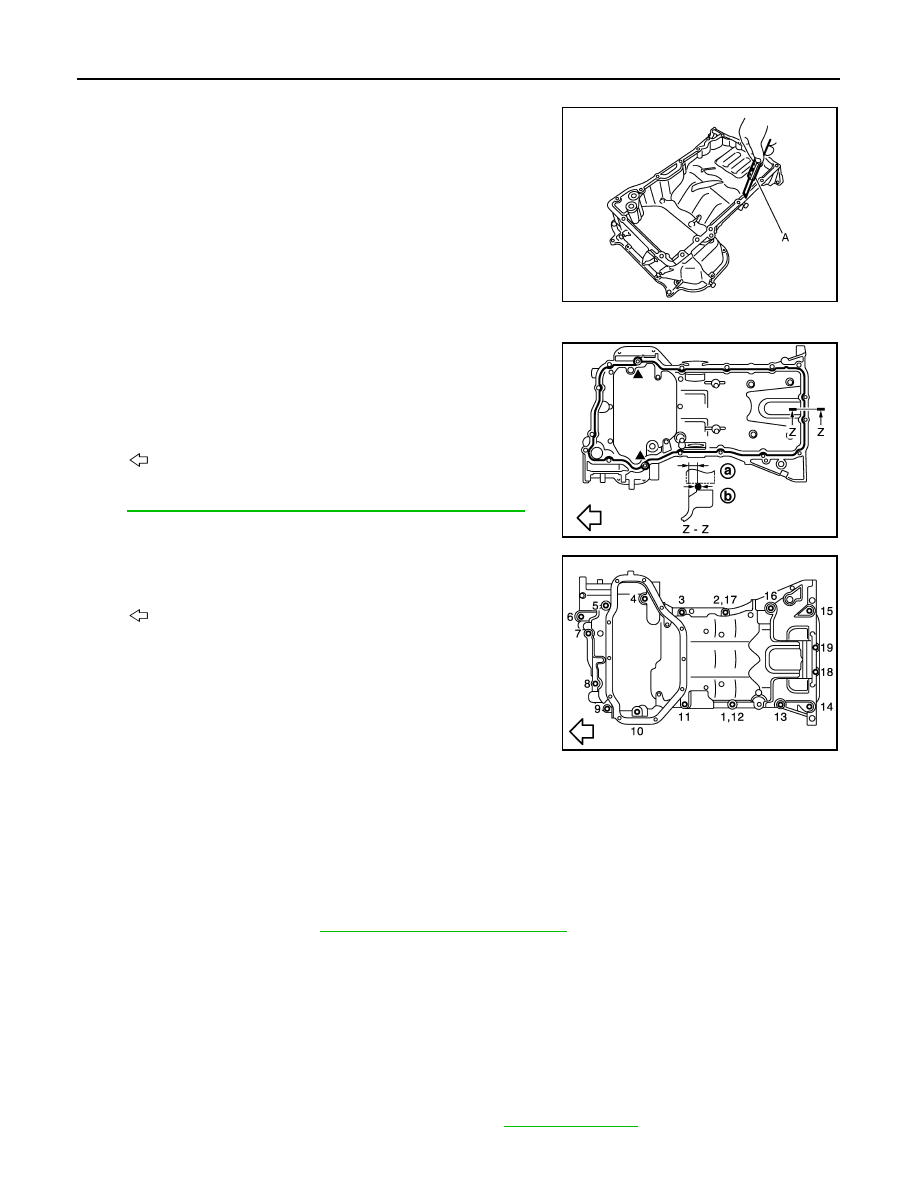
a.
Use a scraper (A) to remove old liquid gasket from mating sur-
faces.
• Also remove the old liquid gasket from mating surface of cylin-
der block.
• Remove old liquid gasket from the bolt holes and threads.
CAUTION:
Never scratch or damage the mating surfaces when clean-
ing off old liquid gasket.
b.
Install new O-rings on the bottom of cylinder block and oil pump.
c.
Apply a continuous bead of liquid gasket with tube presser
(commercial service tool) to the cylinder block mating surfaces
of oil pan (upper) to a limited portion as shown in the figure.
Use Genuine RTV Silicone Sealant or an equivalent. Refer
to
GI-16, "Recommended Chemical Products and Sealants"
CAUTION:
Attaching must be done within 5 minutes after coating.
d.
Tighten mounting bolts in numerical order as shown in the fig-
ure.
CAUTION:
Install avoiding misalignment of O-rings.
NOTE:
Tighten mounting bolts No. 1 and 2 in two steps. The numerical
order No. 12 and 17 shown second steps.
• There are three types of mounting bolts. Refer to the following
for locating bolts.
e.
Tighten transmission joint bolts.
f.
Install rear plate cover.
3.
Install oil strainer.
4.
Install oil pan (lower). Refer to
EM-189, "Removal and Installation"
.
5.
Install in the reverse order of removal.
NOTE:
At least 30 minutes after oil pan is installed, pour engine oil.
Inspection
INFOID:0000000005245249
INSPECTION AFTER DISASSEMBLY
Clean oil strainer if any object is attached.
INSPECTION AFTER ASSEMBLY
1.
Check the engine oil level and adjust engine oil. Refer to
.
JPBIA0027ZZ
a
: 5.5 - 7.5 mm (0.217 - 0.295 in)
b
:
φ
4.0 - 5.0 mm (0.157 - 0.197 in)
: Engine front
: Engine front
M6
×
30 mm. (1.18 in)
: 18, 19
M8
×
100 mm (3.94 in)
: 3, 4, 5, 7, 10, 11, 14, 15
M8
×
45 mm (1.77 in)
: Except the above
JPBIA2092ZZ
JPBIA2089ZZ
OIL PAN (UPPER)
EM-211
< UNIT DISASSEMBLY AND ASSEMBLY >
[VK50VE]
C
D
E
F
G
H
I
J
K
L
M
A
EM
N
P
O
2.
Start engine, and check there is no leakage of engine oil.
3.
Stop engine and wait for 15 minutes.
4.
Check the engine oil level again. Refer to
Нет комментариевНе стесняйтесь поделиться с нами вашим ценным мнением.
Текст