Infiniti FX35, FX50 (S51). Manual — part 611
DIFFERENTIAL ASSEMBLY
DLN-279
< UNIT DISASSEMBLY AND ASSEMBLY >
[REAR FINAL DRIVE: R230]
C
E
F
G
H
I
J
K
L
M
A
B
DLN
N
O
P
3.
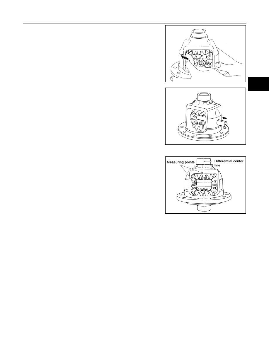
Install side gears and thrust washers into differential case.
CAUTION:
Make sure that the circular clip is installed to side gears.
4.
Align 2 pinion mate gears in diagonally opposite positions, then
rotate and install them into differential case after installing thrust
washer to pinion mate gear.
5.
Align the lock pin holes on differential case with shaft, and install
pinion mate shaft.
6.
Measure side gear end play. If necessary, select the appropriate side gear thrust washers.
a.
Place differential case straight up so that side gear to be mea-
sured comes upward.
SDIA2025E
SDIA0195J
JPDID0205GB
DLN-280
< UNIT DISASSEMBLY AND ASSEMBLY >
[REAR FINAL DRIVE: R230]
DIFFERENTIAL ASSEMBLY
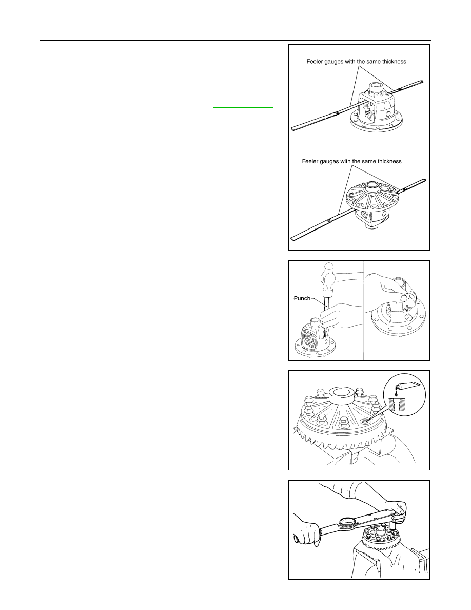
b.
Using feeler gauge, measure the clearance between side gear
back and differential case at 3 different points, while rotating
side gear. Average the 3 readings, and then measure the clear-
ance of the other side as well.
CAUTION:
To prevent side gear from tilting, insert feeler gauges with
the same thickness from both sides.
c.
If the back clearance is outside the specification, use a thicker/
thinner side gear thrust washer to adjust.
CAUTION:
Select a side gear thrust washer for right and left individu-
ally.
7.
Drive a lock pin into pinion mate shaft, using a punch.
Make sure lock pin is flush with differential case.
CAUTION:
Never reuse lock pin.
8.
Apply thread locking sealant into the thread hole of drive gear.
Use Genuine High Strength Thread Locking Sealant or equiva-
lent. Refer to
GI-16, "Recommended Chemical Products and
.
CAUTION:
Clean and degrease drive gear back and threaded holes
sufficiently.
9.
Install the drive gear to differential case.
CAUTION:
Align the matching mark of differential case and drive gear.
10. Tighten the mounting bolts with the following procedure.
CAUTION:
Apply anti-corrosin oil to the thread and seat of mounting
bolts.
a.
Tighten the bolts in a crisscross fashion to the specified torque.
b.
Tighten the bolts additionally to the specified angle.
Standard
Side gear back clearance
: Refer to
.
When the back clearance
is large:
Use a thicker thrust wash-
er.
When the back clearance
is small:
Use a thinner thrust wash-
er.
PDIA0576E
SPD030
SDIA2594E
Drive gear mounting
bolts tightening torque
: 78.5 N•m (8.0 kg-m, 58 ft-lb)
SDIA0247J
DIFFERENTIAL ASSEMBLY
DLN-281
< UNIT DISASSEMBLY AND ASSEMBLY >
[REAR FINAL DRIVE: R230]
C
E
F
G
H
I
J
K
L
M
A
B
DLN
N
O
P
CAUTION:
Check the tightening angle using the angle wrench [SST: KV10112100 (BT-8653-A)]. Never make
judgment by visual inspection.
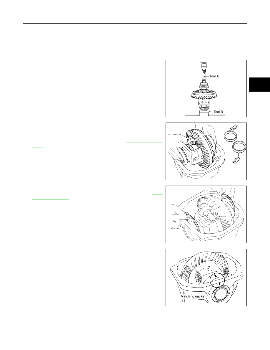
11. Press side bearing inner races to differential case, using the drift
(A) and the base (B).
CAUTION:
Never reuse side bearing inner race.
12. Install differential case assembly with side bearing outer races
into gear carrier.
13. Measure side bearing preload. If necessary, select the appropri-
ate side bearing adjusting washers. Refer to
.
14. Insert selected left and right side bearing adjusting washers in
place between side bearings and gear carrier. Refer to
15. Align matching marks on bearing cap with that on gear carrier.
16. Install bearing caps and tighten bearing cap mounting bolts.
Drive gear mounting
bolts tightening angle
: 31 to 36 degree
A
: Drift [SST: KV40100621 (J-25273)]
B
: Base [SST: ST30901000 (J-26010-01)]
SPD353
SPD527
SPD558
SDIA1795E
DLN-282
< UNIT DISASSEMBLY AND ASSEMBLY >
[REAR FINAL DRIVE: R230]
DIFFERENTIAL ASSEMBLY
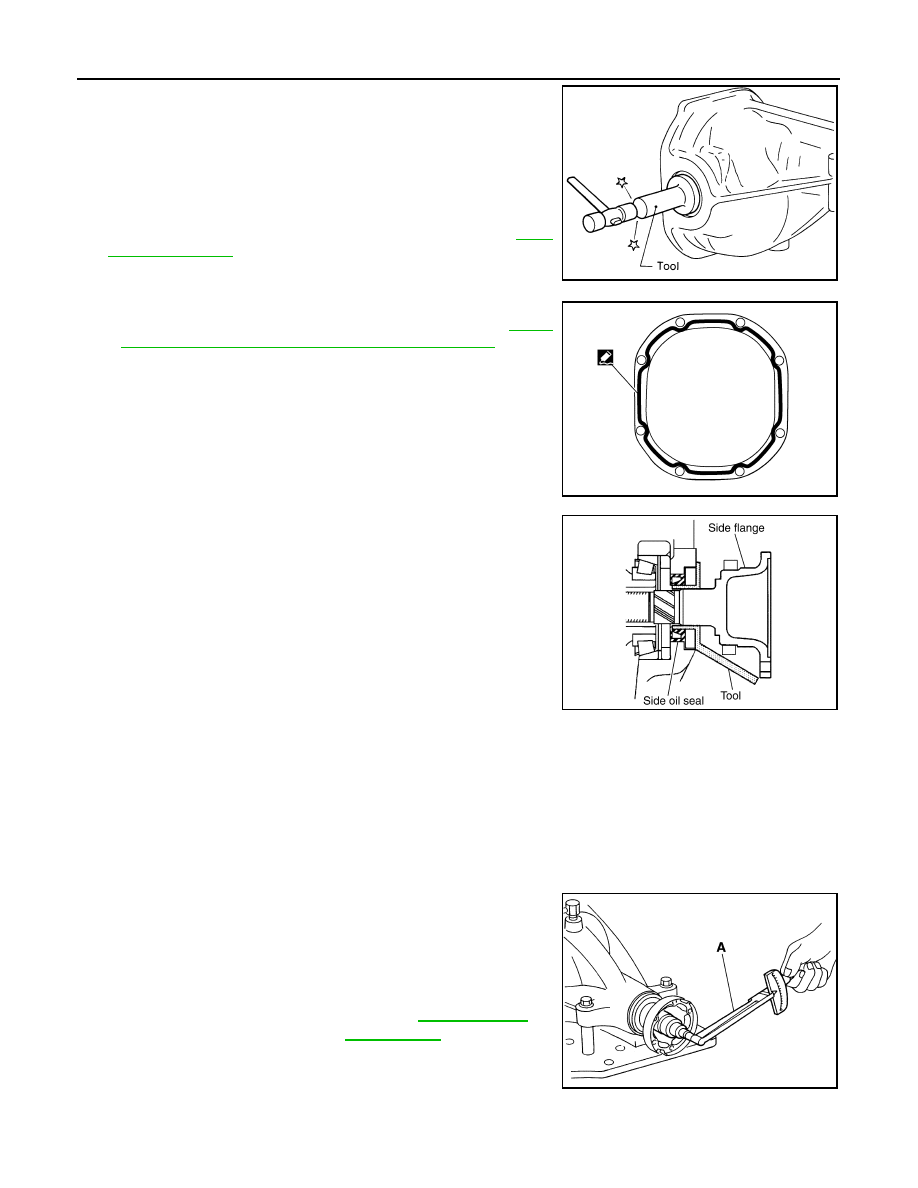
17. Using the drift (A) [SST: ST35271000 (
—
)], drive side oil
seals until it becomes flush with the case end.
CAUTION:
• Never reuse oil seal.
• When installing, never incline oil seal.
• Apply multi-purpose grease onto oil seal lips, and gear oil
onto the circumference of oil seal.
18. Check and adjust drive gear runout, tooth contact, drive gear to
drive pinion backlash, and total preload torque. Refer to
Recheck above items. Readjust the above description, if neces-
sary.
19. Apply sealant (A) to mating surface of rear cover.
• Use Genuine Silicone RTV or equivalent. Refer to
"Recommended Chemical Products and Sealants"
.
CAUTION:
Remove old sealant adhering to mounting surfaces. Also
remove any moisture, oil, or foreign material adhering to
application and mounting surfaces.
20. Install rear cover on gear carrier and tighten mounting bolts.
21. Install side flange with the following procedure.
a.
Attach the protector [SST: KV38107900 (J-39352)] to side oil
seal.
b.
After the side flange is inserted and the serrated part of side
gear has engaged the serrated part of flange, remove the pro-
tector.
c.
Insert the side flange until the serrated part of the side flange
has engaged the serrated part of the side gear and remove the
protector.
NOTE:
When installation is completed, driving sound of the side flange
turns into a sound that seems to affect the whole final drive.
Adjustment
INFOID:0000000005249281
TOTAL PRELOAD TORQUE
Before inspection and adjustment, drain gear oil.
1.
Secure final drive assembly onto an attachment [SST: KV38100800 (J-25604-01)].
2.
Remove side flanges.
3.
Rotate drive pinion back and forth 2 to 3 times to check for unusual noise and rotation malfunction.
4.
Rotate drive pinion at least 20 times to check for smooth opera-
tion of the bearing.
5.
Measure total preload with the preload gauge (A) [SST:
ST3127S000 (J-25765-A)].
NOTE:
Total preload torque = Pinion bearing preload torque + Side
bearing preload torque
• If measured value is out of the specification, disassemble it to check and adjust each part. Adjust the
pinion bearing preload and side bearing preload.
SPD560
PDIA0961E
SDIA0822E
Standard
Total preload torque
: Refer to
PDIA0766J
Нет комментариевНе стесняйтесь поделиться с нами вашим ценным мнением.
Текст