Infiniti FX35, FX50 (S51). Manual — part 609
SIDE OIL SEAL
DLN-271
< REMOVAL AND INSTALLATION >
[REAR FINAL DRIVE: R230]
C
E
F
G
H
I
J
K
L
M
A
B
DLN
N
O
P
SIDE OIL SEAL
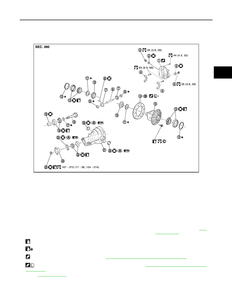
Exploded View
INFOID:0000000005249274
1.
Rear cover
2.
Gasket
3.
Filler plug
4.
Bearing cap
5.
Drain plug
6.
Pinion mate shaft
7.
Pinion mate gear
8.
Lock pin
9.
Pinion mate thrust washer
10. Side gear
11.
Side gear thrust washer
12. Side bearing
13. Side bearing adjusting washer
14. Drive gear
15. Differential case
16. Drive pinion
17. Pinion height adjusting washer
18. Pinion rear bearing
19. Collapsible spacer
20. Side oil seal
21. Gear carrier
22. Pinion front bearing
23. Front oil seal
24. Companion flange
25. Drive pinion lock nut
A.
Oil seal lip
B.
Screw hole
C.
Comply with the assembly proce-
dure when tightening. Refer to
: Apply gear oil.
: Apply anti-corrosion oil.
: Apply Genuine Silicone RTV or equivalent. Refer to
GI-16, "Recommended Chemical Products and Sealants"
.
: Apply Genuine High Strength Thread Locking Sealant or equivalent. Refer to
GI-16, "Recommended Chemical Products
Refer to
for symbols not described above.
JPDID0289GB
DLN-272
< REMOVAL AND INSTALLATION >
[REAR FINAL DRIVE: R230]
SIDE OIL SEAL
Removal and Installation
INFOID:0000000005249275
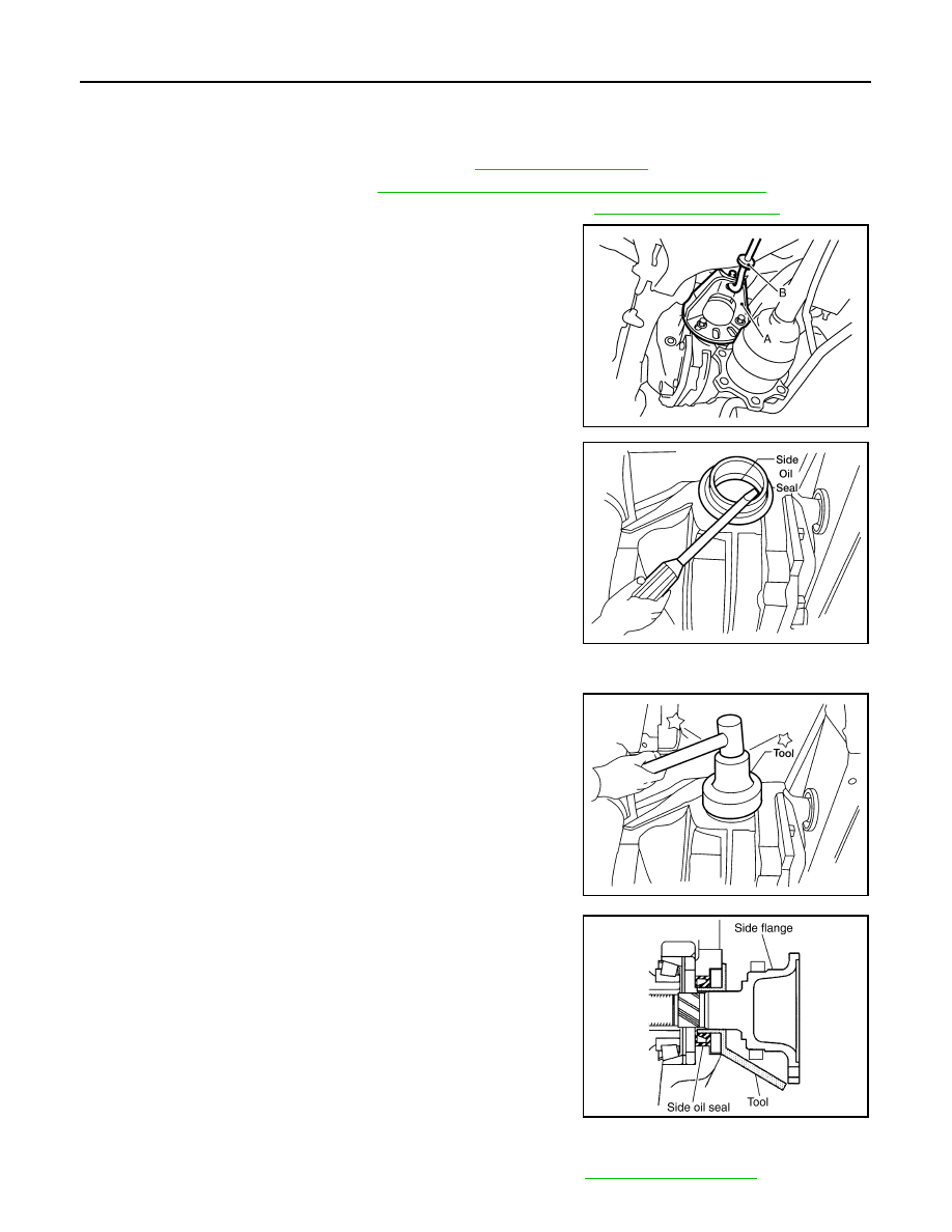
REMOVAL
1.
Remove center muffler with a power tool. Refer to
2.
Remove rear wheel sensor. Refer to
BRC-132, "REAR WHEEL SENSOR : Exploded View"
.
3.
Remove the drive shaft from the rear final drive assembly. Refer to
4.
Remove the side flange using sliding hammer and attachment.
5.
Remove the side oil seal using suitable tool.
CAUTION:
Never damage gear carrier.
INSTALLATION
1.
Apply multi-purpose grease to the lips of the new side oil seal.
Then drive the new side oil seal in evenly until it becomes flush
with the gear carrier using the drift [SST: ST35271000 (
—
)].
CAUTION:
• Never reuse side oil seal.
• Never incline the new side oil seal when installing.
2.
Install the side flange using Tool.
a.
Install the protector [SST: KV38107900 (J-39352)] to the side oil
seal as shown.
b.
Insert the side flange until the serrated part of the side flange
has engaged the serrated part of the side gear and remove the
Tool.
c.
Drive in the side flange using suitable tool.
NOTE:
Installation is completed when the driving sound of the side
flange turns into a sound which seems to affect the whole rear
final drive assembly.
3.
Installation of the remaining components is in the reverse order of removal.
CAUTION:
Check the differential gear oil level after installation. Refer to
.
A
: Attachment [SST: ST36230000 (J-25840
−
A)]
B
: Sliding hammer [SST: KV40104100 (
—
)]
JSDIA0105ZZ
LDIA0109E
LDIA0111E
SDIA0822E

REAR FINAL DRIVE
DLN-273
< UNIT REMOVAL AND INSTALLATION >
[REAR FINAL DRIVE: R230]
C
E
F
G
H
I
J
K
L
M
A
B
DLN
N
O
P
UNIT REMOVAL AND INSTALLATION
REAR FINAL DRIVE
Exploded View
INFOID:0000000005249276
Removal and Installation
INFOID:0000000005249277
REMOVAL
1.
Remove center muffler with a power tool. Refer to
2.
Remove stabilizer bar with a power tool. Refer to
3.
Remove rear propeller shaft from the final drive. Refer to
.
4.
Remove drive shaft from final drive with a power tool. Then sus-
pend it by wire, etc. Refer to
.
5.
Remove breather hose from the final drive.
6.
Remove rear wheel sensor. Refer to
.
1.
Rear final drive assembly
2.
Upper stopper
3.
Lower stopper
4.
Washer
: Vehicle front
Refer to
JSDIA0820GB
SDIA1094E
DLN-274
< UNIT REMOVAL AND INSTALLATION >
[REAR FINAL DRIVE: R230]
REAR FINAL DRIVE
7.
Set a suitable jack to rear final drive assembly.
CAUTION:
Never place a jack under the rear cover (aluminum case).
8.
Remove the mounting bolts and nuts connecting to the suspen-
sion member with a power tool. And then, remove rear final
drive assembly.
CAUTION:
Secure rear final drive assembly to a suitable jack while
removing it.
INSTALLATION
Note the following, and installation is in the reverse order of removal.
CAUTION:
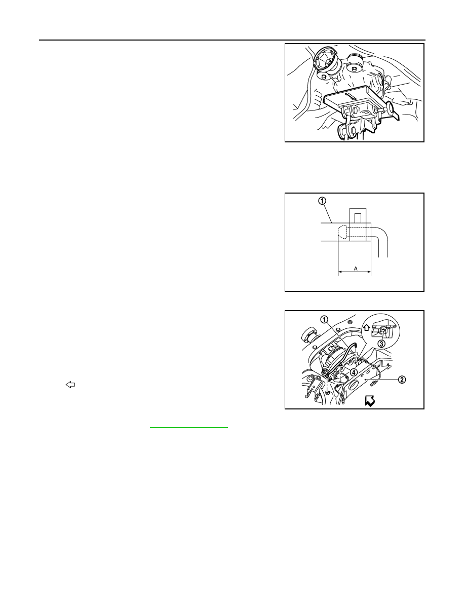
Check that there are no pinched or restricted areas on the breather hose caused by bending or wind-
ing when installing it.
• Install the breather hose (1) to breather connector until dimension
(A) shown as follows.
CAUTION:
• Never reuse hose clamp.
• Install the hose clamp at the final drive side, with the tab fac-
ing downward.
• Install the hose clamp at the suspension member side, with the tab facing downward.
• If remove breather connector, install breather hose (1) as shown in
the figure.
- For installation, insert the resin connector into rear suspension
member (2). Install the metal connector (3) in rear cover so that the
hose insertion side faces the left side of the vehicle as shown in
the figure. Insert the hose clip (4) into rear suspension member.
Arrange the breather hose to pass by over wheel sensor harness.
CAUTION:
Never reuse breather connector and hose clip.
• When oil leaks while removing final drive assembly, check oil level
after the installation. Refer to
JSDIA0131ZZ
A:
Final drive side
: 20 mm (0.79 in)
Suspension member
side
: 20.5 mm (0.807 in)
: Vehicle front
JPDID0020ZZ
JSDIA0860ZZ
Нет комментариевНе стесняйтесь поделиться с нами вашим ценным мнением.
Текст