Infiniti FX35, FX50 (S51). Manual — part 227
PRECAUTIONS
BR-5
< PRECAUTION >
C
D
E
G
H
I
J
K
L
M
A
B
BR
N
O
P
5.
When the repair work is completed, re-connect both battery cables. With the brake pedal released, turn
the push-button ignition switch from ACC position to ON position, then to LOCK position. (The steering
wheel will lock when the push-button ignition switch is turned to LOCK position.)
6.
Perform self-diagnosis check of all control units using CONSULT-III.
Precaution for Procedure without Cowl Top Cover
INFOID:0000000005234160
When performing the procedure after removing cowl top cover, cover
the lower end of windshield with urethane, etc.
Precaution for Brake System
INFOID:0000000005234161
WARNING:
Clean any dust from the front brake and rear brake with a vacuum dust collector. Never blow with com-
pressed air.
CAUTION:
• Brake fluid use refer to
MA-12, "Fluids and Lubricants"
• Never reuse drained brake fluid.
• Never spill or splash brake fluid on painted surfaces. Brake fluid may seriously damage paint. Wipe it
off immediately and wash with water if it gets on a painted surface.
• After pressing the brake pedal more deeply or harder than normal driving, such as air bleeding,
check each item of brake pedal. Adjust brake pedal if it is outside the standard value.
• Always clean with new brake fluid when cleaning the master cylinder, brake caliper and other com-
ponents.
• Never use mineral oils such as gasoline or light oil to clean. They may damage rubber parts and
cause improper operation.
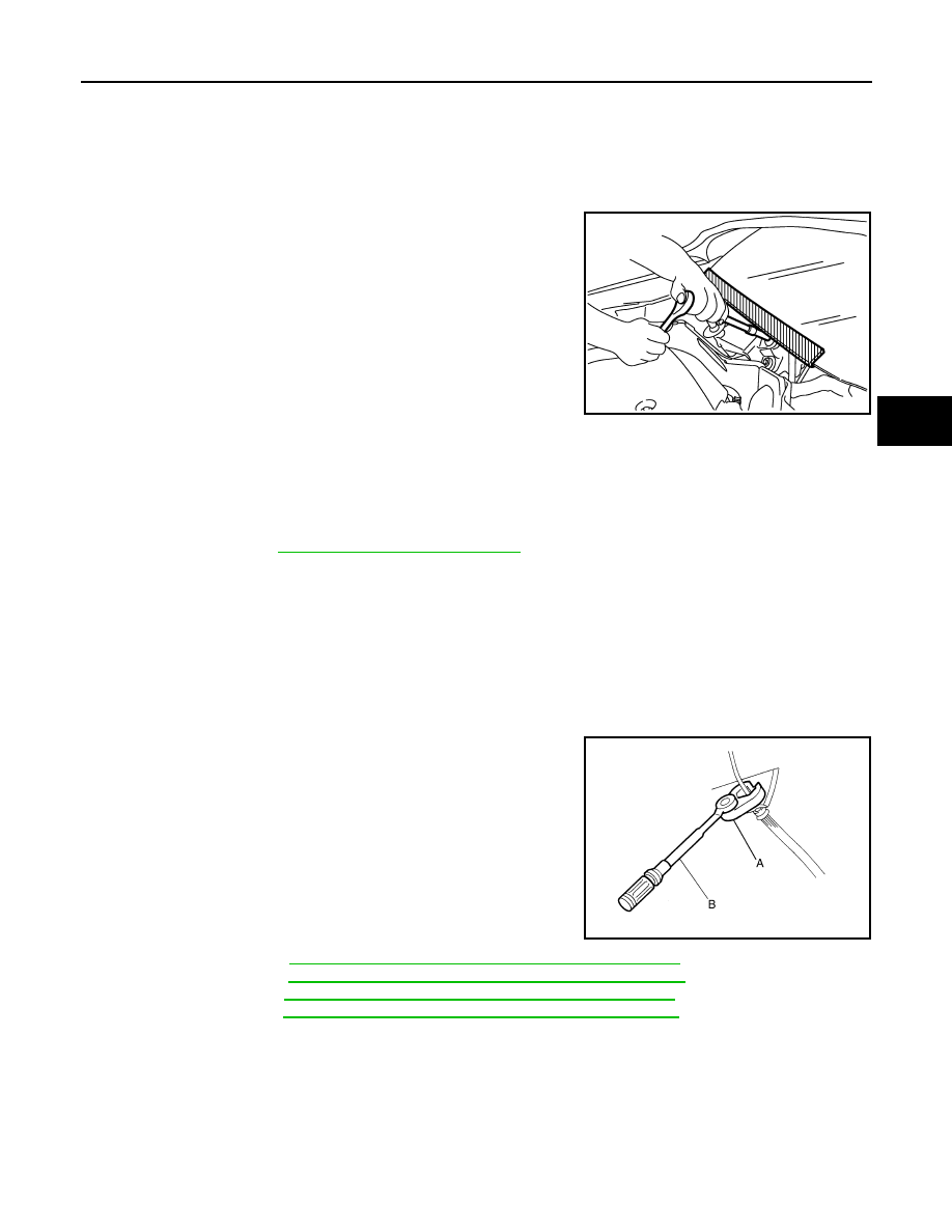
• Always loosen the brake tube flare nut with a flare nut wrench.
• Tighten the brake tube flare nut to the specified torque with a
crowfoot (A) and torque wrench (B).
• Always confirm the specified tightening torque when install-
ing the brake pipes.
• Turn the ignition switch OFF and disconnect the ABS actuator
and electric unit (control unit) connector or the battery nega-
tive terminal before performing the work.
• Check that no brake fluid leakage is present after replacing
the parts.
• Burnish the brake contact surfaces after refinishing or replac-
ing rotors, after replacing pads, or if a soft pedal occurs at
very low mileage.
- Front brake pad: refer to
BR-14, "BRAKE PAD : Inspection and Adjustment"
- Front disc rotor: refer to
BR-14, "DISC ROTOR : Inspection and Adjustment"
- Rear brake pad: refer to
BR-16, "BRAKE PAD : Inspection and Adjustment"
- Rear disc rotor: refer to
BR-16, "DISC ROTOR : Inspection and Adjustment"
.
PIIB3706J
JPFIA0001ZZ
BR-6
< PREPARATION >
PREPARATION
PREPARATION
PREPARATION
Commercial Service Tool
INFOID:0000000005234162
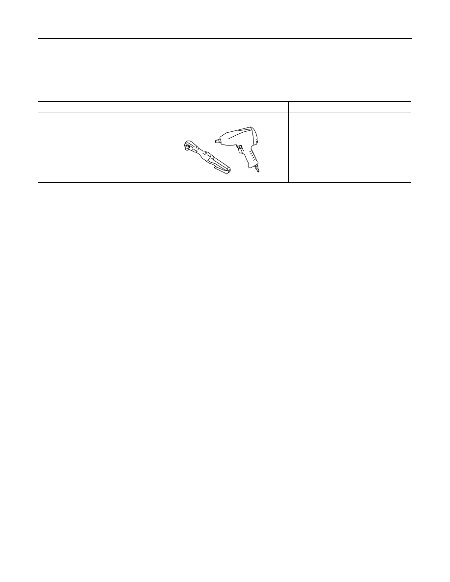
Tool name
Description
Power tool
Loosening bolts and nuts
PBIC0190E
BRAKE PEDAL
BR-7
< PERIODIC MAINTENANCE >
C
D
E
G
H
I
J
K
L
M
A
B
BR
N
O
P
PERIODIC MAINTENANCE
BRAKE PEDAL
Inspection and Adjustment
INFOID:0000000005234163
INSPECTION
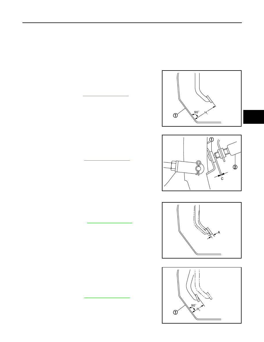
Brake Pedal Height
Check the brake pedal height (H
1
) between the dash lower panel (1)
and the brake pedal upper surface.
CAUTION:
Remove the floor trim.
Stop Lamp Switch and ASCD Brake Switch
Check the clearance (C) between stopper rubber (1) and stop lamp
switch and ASCD brake switch (2) threaded end.
CAUTION:
The stop lamp must be turned off when the brake pedal is
released.
NOTE:
Pull the brake pedal pad to make the clearance between stopper
rubber and stop lamp switch and ASCD brake switch threaded end.
Brake Pedal Play
Press the brake pedal. Check the brake pedal play (A).
Depressed Brake Pedal Height
Check the brake pedal height (H
2
) between the dash lower panel (1)
and the brake pedal upper surface when depressing the brake pedal
at 490 N (50 kg, 110 lb) while turning engine ON.
CAUTION:
Remove the floor trim.
Standard
H
1
: Refer to
JPFIA0065ZZ
Standard
C
: Refer to
.
JPFIA0122ZZ
Standard
A
: Refer to
.
JPFIA0121ZZ
Standard
H
2
: Refer to
.
JPFIA0068ZZ
BR-8
< PERIODIC MAINTENANCE >
BRAKE PEDAL
ADJUSTMENT
Brake Pedal Height
1.
Remove instrument lower panel LH. Refer to
2.
Disconnect the stop lamp switch and ASCD brake switch harness connector.
3.
Turn the stop lamp switch and ASCD brake switch 45
°
counterclockwise.
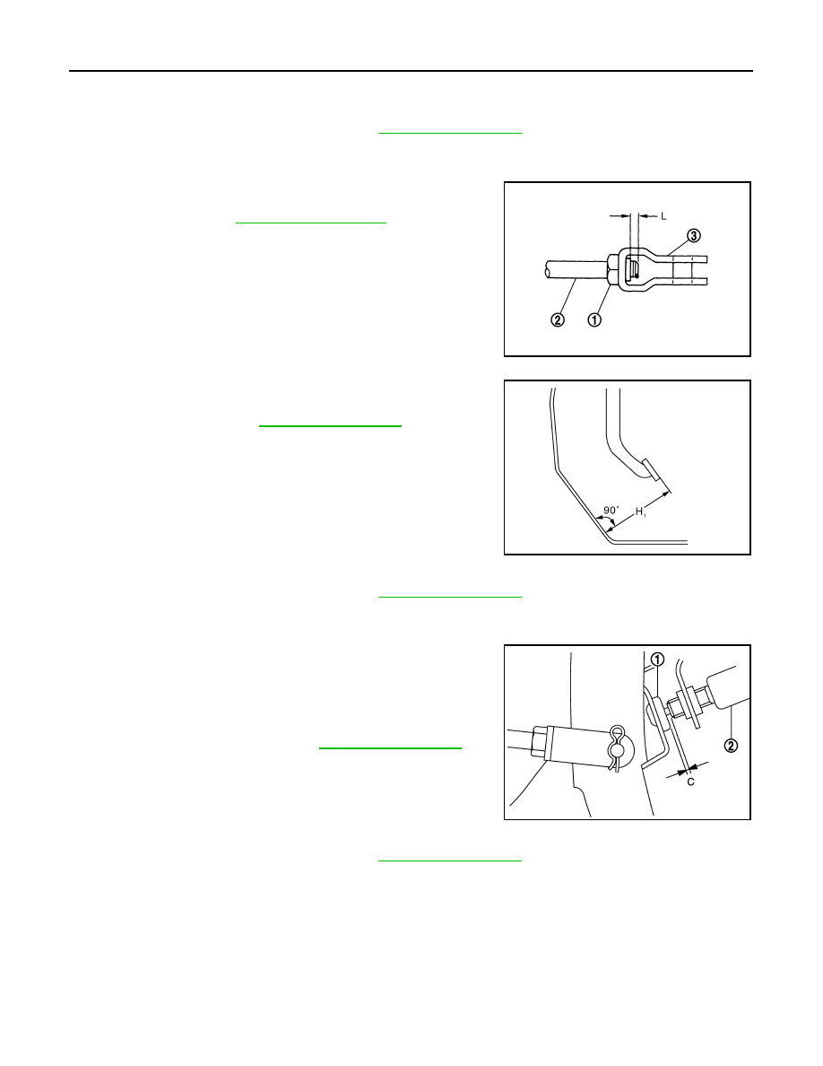
4.
Loosen the input rod lock nut (1). Adjust the brake pedal height
(H
1
) to the specification. Tighten the input rod lock nut to the
specification. Refer to
.
CAUTION:
The threaded end of the input rod (2) must project to the
inner side (L) of the clevis (3).
Stop Lamp Switch and ASCD Brake Switch
1.
Remove instrument lower panel LH. Refer to
2.
Disconnect the stop lamp switch and ASCD brake switch harness connector.
3.
Turn the stop lamp switch and ASCD brake switch 45
°
counterclockwise.
4.
Press-fit stop lamp switch and ASCD brake switch (2) until stop
lamp switch and ASCD brake switch hits the stopper rubber (1)
45
°
clockwise.
CAUTION:
• The clearance (C) between the stopper rubber and stop
lamp switch and ASCD brake switch threaded end must
be the specified value. Refer to
.
• The stop lamp must be turned off when the brake pedal is
released.
Brake Pedal Play
1.
Remove instrument lower panel LH. Refer to
2.
Disconnect the stop lamp switch and ASCD brake switch harness connector.
3.
Turn the stop lamp switch and ASCD brake switch 45
°
counterclockwise.
JPFIA0003ZZ
Standard
H
1
: Refer to
.
JPFIA0279ZZ
JPFIA0122ZZ
Нет комментариевНе стесняйтесь поделиться с нами вашим ценным мнением.
Текст