Infiniti FX35, FX50 (S51). Manual — part 538
REAR DOOR LOCK
DLK-275
< REMOVAL AND INSTALLATION >
C
D
E
F
G
H
I
J
L
M
A
B
DLK
N
O
P
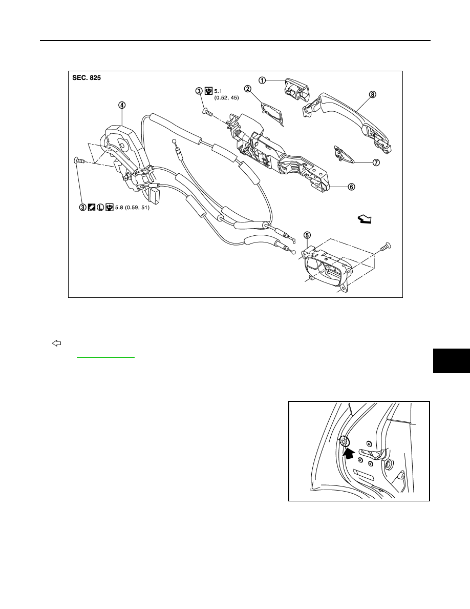
OUTSIDE HANDLE : Exploded View
INFOID:0000000005239771
OUTSIDE HANDLE : Removal and Installation
INFOID:0000000005239772
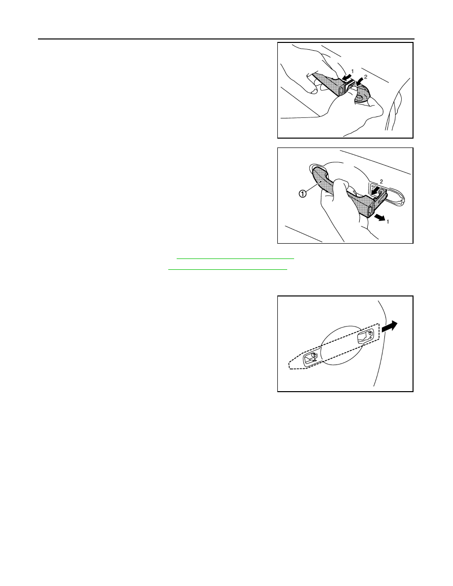
REMOVAL
1.
Disconnect rear door weather-strip to see door side grommet.
2.
Remove door side grommet, and loosen TORX bolt from grom-
met hole.
1.
Outside handle escutcheon
2.
Rear gasket
3.
TORX bolt
4.
Door lock assembly
5.
Inside handle
6.
Outside handle bracket
7.
Front gasket
8.
Outside handle
: Vehicle front
Refer to
JMKIA2645GB
JMKIA2651ZZ
DLK-276
< REMOVAL AND INSTALLATION >
REAR DOOR LOCK
3.
While pulling outside handle, remove outside handle escutch-
eon.
4.
While pulling outside handle (1), slide toward rear of vehicle to
remove outside handle.
5.
Remove rear door finisher. Refer to
INT-14, "Removal and Installation"
.
6.
Remove sealing screen. Refer to
GW-24, "Removal and Installation"
.
7.
Fully close rear door glass.
8.
Remove front gasket and rear gasket.
9.
Slide toward rear of vehicle to remove outside handle bracket.
10. Disconnect door lock cable from outside handle bracket.
INSTALLATION
Install in the reverse order of removal.
CAUTION:
• Check door lock cable is properly engaged with outside handle bracket.
• After installation, check door open/close, lock/unlock operation.
JMKIA0560ZZ
JMKIA0524ZZ
JMKIA2652ZZ
BACK DOOR LOCK
DLK-277
< REMOVAL AND INSTALLATION >
C
D
E
F
G
H
I
J
L
M
A
B
DLK
N
O
P
BACK DOOR LOCK
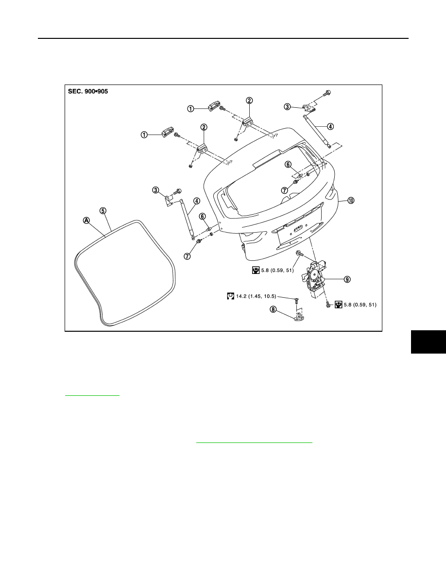
Exploded View
INFOID:0000000005239773
Removal and Installation
INFOID:0000000005239774
REMOVAL
1.
Remove back door finisher inner. Refer to
INT-32, "Removal and Installation"
2.
Disconnect back door lock assembly connectors.
3.
Remove back door lock mounting bolts, and then remove back door lock assembly.
INSTALLATION
Install in the reverse order of removal.
CAUTION:
After installation, check back door open/close, lock/unlock operation.
1.
Back door hinge cover (LH/RH)
2.
Back door hinge (LH/RH)
3.
Back door stay bracket (LH/RH)
4.
Back door stay (LH/RH)
5.
Back door weather-strip
6.
Stud ball (LH/RH)
7.
Bumper rubber (side) (LH/RH)
8.
Back door striker
9.
Back door lock assembly
10. Back door assembly
A
: Center mark
Refer to
for symbols in the figure.
JMKIA2642GB
DLK-278
< REMOVAL AND INSTALLATION >
FUEL FILLER LID OPENER
FUEL FILLER LID OPENER
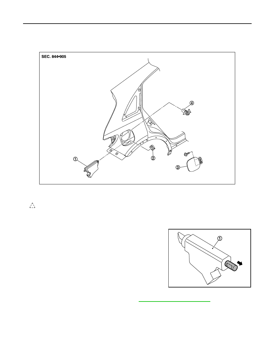
Exploded View
INFOID:0000000005239775
Removal and Installation
INFOID:0000000005239776
NOTE:
When fuel filler lid lock actuator (1) is a defective operation, pull the
rod to open fuel filler lid.
REMOVAL
1.
Remove luggage side finisher lower (RH). Refer to
INT-29, "Removal and Installation"
2.
Pull and remove lock & cable assembly forward, while pushing the pawls.
3.
Rotate lock nut counterclockwise, and then remove lock nut.
4.
Push fuel filler lid lock actuator behind the vehicle, while pushing the pawl.
5.
Disconnect harness connector and remove fuel filler lid lock actuator.
6.
Remove mounting screws, and then remove fuel filler lid.
1.
Fuel filler lid lock actuator
2.
Lock nut
3.
Fuel filler lid assembly
4.
Lock & cable assembly
: Pawl
JMKIA2646ZZ
JMKIA1960ZZ
Нет комментариевНе стесняйтесь поделиться с нами вашим ценным мнением.
Текст