Infiniti FX35, FX50 (S51). Manual — part 537
FRONT DOOR LOCK
DLK-271
< REMOVAL AND INSTALLATION >
C
D
E
F
G
H
I
J
L
M
A
B
DLK
N
O
P
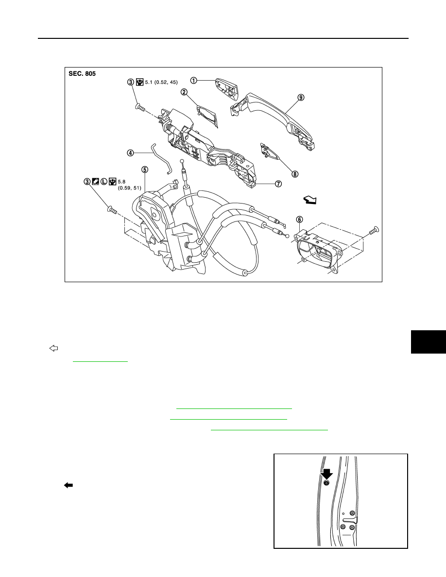
OUTSIDE HANDLE : Exploded View
INFOID:0000000005239765
OUTSIDE HANDLE : Removal and Installation
INFOID:0000000005239766
REMOVAL
1.
Remove front door finisher. Refer to
INT-11, "Removal and Installation"
2.
Remove front door glass. Refer to
GW-18, "Removal and Installation"
3.
Remove front door module assembly. Refer to
GW-21, "Removal and Installation"
.
4.
Disconnect door antenna and door request switch connector, and then remove harness clamp (models
with Intelligent Key system) on outside handle bracket.
5.
Remove door side grommet, and loosen TORX bolt from grom-
met hole.
1.
Door key cylinder assembly (driver
side)
Outside handle escutcheon (passen-
ger side)
2.
Rear gasket
3.
TORX bolt
4.
Key rod (driver side)
5.
Door lock assembly
6.
Inside handle
7.
Outside handle bracket
8.
Front gasket
9.
Outside handle
: Vehicle front
Refer to
JMKIA2917GB
: TORX bolt
JMKIA2094ZZ

DLK-272
< REMOVAL AND INSTALLATION >
FRONT DOOR LOCK
6.
Reach in to separate key rod (2) connection [on the door key
cylinder assembly (1)] (driver side).
7.
While pulling outside handle, remove door key cylinder assem-
bly (driver side) or outside handle escutcheon (passenger side).
8.
While pulling outside handle (1), slide toward rear of vehicle to
remove outside handle.
9.
Remove front gasket and rear gasket.
10. Slide toward rear of vehicle to remove outside handle bracket.
11. Disconnect door lock cable from outside handle bracket.
INSTALLATION
Install in the reverse order of removal.
CAUTION:
• When installing key rod, rotate key rod holder until a click is felt.
• Check door lock cable is properly engaged with outside handle bracket.
• After installation, check door open/close, lock/unlock operation.
JMKIA0553ZZ
JMKIA0560ZZ
JMKIA0524ZZ
JMKIA2652ZZ
REAR DOOR LOCK
DLK-273
< REMOVAL AND INSTALLATION >
C
D
E
F
G
H
I
J
L
M
A
B
DLK
N
O
P
REAR DOOR LOCK
DOOR LOCK
DOOR LOCK : Exploded View
INFOID:0000000005239767
DOOR LOCK : Removal and Installation
INFOID:0000000005239768
REMOVAL
1.
Remove outside handle escutcheon, outside handle, rear gasket and front gasket. Refer to
"OUTSIDE HANDLE : Removal and Installation"
2.
Remove rear door finisher. Refer to
INT-14, "Removal and Installation"
.
3.
Remove sealing screen, rear door glass and rear door sash. Refer to
GW-24, "Removal and Installation"
.
4.
Remove outside handle bracket. Refer to
DLK-275, "OUTSIDE HANDLE : Exploded View"
5.
Remove door lock assembly TORX bolts.
6.
Disconnect door lock actuator connector, and then remove door lock assembly.
INSTALLATION
Install in the reverse order of removal.
CAUTION:
• Check door lock cables are properly engaged with inside handle and outside handle.
• After installation, check door open/close, lock/unlock operation.
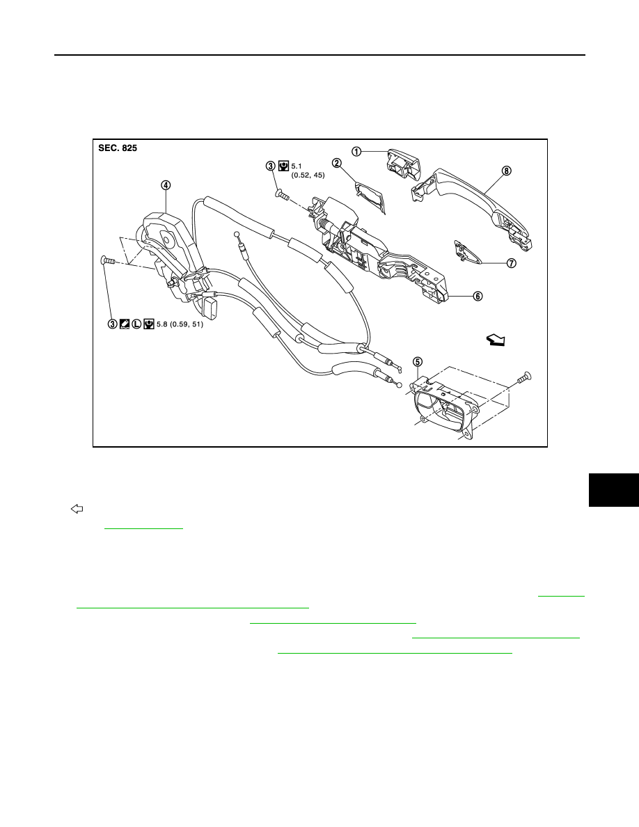
INSIDE HANDLE
1.
Outside handle escutcheon
2.
Rear gasket
3.
TORX bolt
4.
Door lock assembly
5.
Inside handle
6.
Outside handle bracket
7.
Front gasket
8.
Outside handle
: Vehicle front
Refer to
JMKIA2645GB

DLK-274
< REMOVAL AND INSTALLATION >
REAR DOOR LOCK
INSIDE HANDLE : Exploded View
INFOID:0000000005239769
INSIDE HANDLE : Removal and Installation
INFOID:0000000005239770
REMOVAL
1.
Remove rear door finisher. Refer to
INT-14, "Removal and Installation"
.
2.
Disconnect door lock cables from inside handle.
3.
Remove inside handle mounting screws, and then remove inside handle.
INSTALLATION
Install in the reverse order of removal.
CAUTION:
• Check door lock cables are properly engaged with inside handle.
• After installation, check door open/close, lock/unlock operation.
OUTSIDE HANDLE
1.
Outside handle escutcheon
2.
Rear gasket
3.
TORX bolt
4.
Door lock assembly
5.
Inside handle
6.
Outside handle bracket
7.
Front gasket
8.
Outside handle
: Vehicle front
Refer to
for symbols in the figure.
JMKIA2645GB
Нет комментариевНе стесняйтесь поделиться с нами вашим ценным мнением.
Текст