Infiniti FX35, FX50 (S51). Manual — part 890
ELECTRICAL LOAD SIGNAL
EC-1101
< DTC/CIRCUIT DIAGNOSIS >
[VK50VE]
C
D
E
F
G
H
I
J
K
L
M
A
EC
N
P
O
ELECTRICAL LOAD SIGNAL
Description
INFOID:0000000005237604
The electrical load signal (Rear window defogger switch signal, headlamp switch signal, heater fan switch sig-
nal, etc.) is transferred via the CAN communication line.
Component Function Check
INFOID:0000000005237605
1.
CHECK REAR WINDOW DEFOGGER SWITCH FUNCTION
1.
Turn ignition switch ON.
2.
Select “DATA MONITOR” mode with CONSULT-III.
3.
Select “LOAD SIGNAL” and check indication under the following conditions.
Is the inspection result normal?
YES
>> GO TO 2.
NO
>> Go to
EC-1101, "Diagnosis Procedure"
.
2.
CHECK LIGHTING SWITCH FUNCTION
Check “LOAD SIGNAL” indication under the following conditions.
Is the inspection result normal?
YES
>> GO TO 3.
NO
>> Go to
EC-1101, "Diagnosis Procedure"
.
3.
CHECK HEATER FAN CONTROL SWITCH FUNCTION
Select “HEATER FAN SW” and check indication under the following conditions.
Is the inspection result normal?
YES
>> INSPECTION END
NO
>> Go to
EC-1101, "Diagnosis Procedure"
.
Diagnosis Procedure
INFOID:0000000005237606
1.
INSPECTION START
Confirm the malfunctioning circuit (rear window defogger, headlamp or heater fan). Refer to
.
Which circuit is related to the incident?
Rear window defogger>>GO TO 2.
Headlamp>>GO TO 3.
Heater fan>>GO TO 4.
2.
CHECK REAR WINDOW DEFOGGER SYSTEM
.
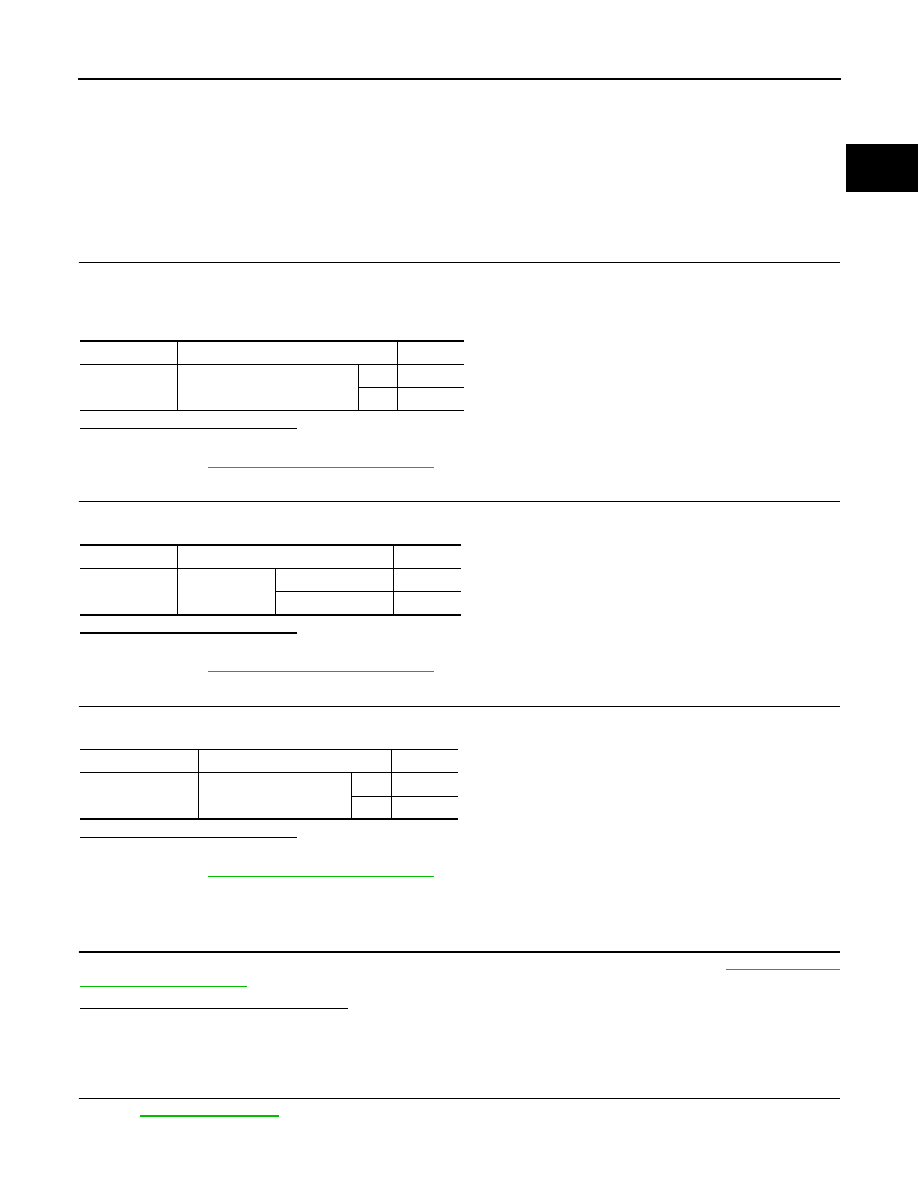
Monitor item
Condition
Indication
LOAD SIGNAL
Rear window defogger switch
ON
ON
OFF
OFF
Monitor item
Condition
Indication
LOAD SIGNAL
Lighting switch
ON at 2nd position
ON
OFF
OFF
Monitor item
Condition
Indication
HEATER FAN SW
Heater fan control switch
ON
ON
OFF
OFF

EC-1102
< DTC/CIRCUIT DIAGNOSIS >
[VK50VE]
ELECTRICAL LOAD SIGNAL
>> INSPECTION END
3.
CHECK HEADLAMP SYSTEM
>> INSPECTION END
4.
CHECK HEATER FAN CONTROL SYSTEM
>> INSPECTION END
FUEL INJECTOR
EC-1103
< DTC/CIRCUIT DIAGNOSIS >
[VK50VE]
C
D
E
F
G
H
I
J
K
L
M
A
EC
N
P
O
FUEL INJECTOR
Description
INFOID:0000000005237607
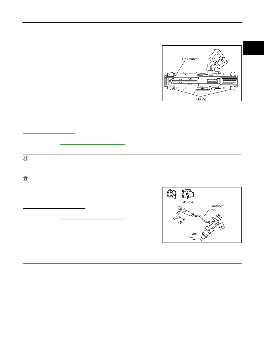
The fuel injector is a small, precise solenoid valve. When the ECM
supplies a ground to the fuel injector circuit, the coil in the fuel injec-
tor is energized. The energized coil pulls the ball valve back and
allows fuel to flow through the fuel injector into the intake manifold.
The amount of fuel injected depends upon the injection pulse dura-
tion. Pulse duration is the length of time the fuel injector remains
open. The ECM controls the injection pulse duration based on
engine fuel needs.
Component Function Check
INFOID:0000000005237608
1.
INSPECTION START
Turn ignition switch to START.
Are any cylinders ignited?
YES
>> GO TO 2.
NO
>> Go to
EC-1103, "Diagnosis Procedure"
.
2.
CHECK FUEL INJECTOR FUNCTION
With CONSULT-III
1.
Start engine.
2.
Perform “POWER BALANCE” in “ACTIVE TEST” mode with CONSULT-III.
3.
Check that each circuit produces a momentary engine speed drop.
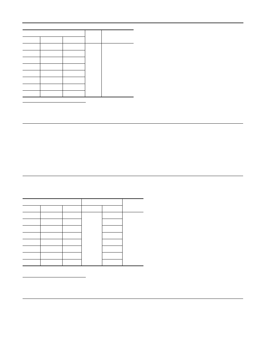
Without CONSULT-III
1.
Start engine.
2.
Listen to each fuel injector operating sound.
Is the inspection result normal?
YES
>> INSPECTION END
NO
>> Go to
EC-1103, "Diagnosis Procedure"
.
Diagnosis Procedure
INFOID:0000000005237609
1.
CHECK FUEL INJECTOR POWER SUPPLY CIRCUIT
1.
Turn ignition switch OFF.
2.
Disconnect fuel injector harness connector.
3.
Turn ignition switch ON.
4.
Check the voltage between fuel injector harness connector and ground.
SEF375Z
Clicking sound should be heard.
PBIB3332E
EC-1104
< DTC/CIRCUIT DIAGNOSIS >
[VK50VE]
FUEL INJECTOR
Is the inspection result normal?
YES
>> GO TO 3.
NO
>> GO TO 2.
2.
DETECT MALFUNCTIONING PART
Check the following.
• Harness connectors F60, F121
• Harness connectors E10, F10
• IPDM E/R harness connector E7
• 10 A fuse (No. 44)
• Harness for open or short between fuel injector and fuse
>> Repair open circuit, short to ground or short to power in harness or connectors.
3.
CHECK FUEL INJECTOR OUTPUT SIGNAL CIRCUIT FOR OPEN AND SHORT
1.
Turn ignition switch OFF.
2.
Disconnect ECM harness connector.
3.
Check the continuity between fuel injector harness connector and ECM harness connector.
4.
Also check harness for short to ground and short to power.
Is the inspection result normal?
YES
>> GO TO 5.
NO
>> GO TO 4
4.
DETECT MALFUNCTIONING PART
Check the following.
• Harness connectors F60, F121
• Harness connectors F69, F122
• Harness for open or short between fuel injector and ECM
>> Repair open circuit, short to ground or short to power in harness or connectors.
Fuel injector
Ground
Voltage
Cylinder
Connector
Terminal
1
F123
1
Ground
Battery voltage
2
F124
1
3
F125
1
4
F126
1
5
F127
1
6
F128
1
7
F129
1
8
F130
1
Fuel injector
ECM
Continuity
Cylinder
Connector
Terminal
Connector
Terminal
1
F123
2
F110
25
Existed
2
F124
2
21
3
F125
2
17
4
F126
2
37
5
F127
2
41
6
F128
2
45
7
F129
2
29
8
F130
2
33
Нет комментариевНе стесняйтесь поделиться с нами вашим ценным мнением.
Текст