Infiniti FX35, FX50 (S51). Manual — part 889

COOLING FAN
EC-1097
< DTC/CIRCUIT DIAGNOSIS >
[VK50VE]
C
D
E
F
G
H
I
J
K
L
M
A
EC
N
P
O
3.
Also check harness for short to power.
Is the inspection result normal?
YES
>> GO TO 3.
NO
>> Repair open circuit or short to power in harness or connectors.
3.
CHECK IPDM E/R GROUND CIRCUIT
1.
Disconnect IPDM E/R harness connectors E5, E6.
2.
Check the continuity between IPDM E/R harness connector and ground.
3.
Also check harness for short to power.
Is the inspection result normal?
YES
>> GO TO 4.
NO
>> Repair open circuit or short to power in harness or connectors.
4.
CHECK COOLING FAN CONTROL SIGNAL CIRCUIT
1.
Disconnect IPDM E/R harness connector E9.
2.
Check the continuity between IPDM E/R harness connector and cooling fan control module harness con-
nector.
3.
Also check harness for short to ground and short to power.
Is the inspection result normal?
YES
>> GO TO 5.
NO
>> Repair open circuit, short to ground or short to power in harness or connectors.
5.
CHECK COOLING FAN CONTROL MODULE OUTPUT SIGNAL CIRCUIT
1.
Reconnect all harness connectors disconnected.
2.
Disconnect cooling fan control module harness connectors E301, E303.
3.
Turn ignition switch ON.
4.
Check the voltage between cooling fan control module terminals and ground.
Cooling fan control module
Ground
Continuity
Connector
Terminal
E37
(Cooling fan control module 1)
1
Ground
Existed
E38
(Cooling fan control module 2)
1
IPDM E/R
Ground
Continuity
Connector
Terminal
E5
12
Ground
Existed
E6
41
IPDM E/R
Cooling fan control module
Continuity
Connector
Terminal
Connector
Terminal
E9
97
E37
(Cooling fan control module 1)
2
Existed
E38
(Cooling fan control module 2)
2
Existed
Cooling fan control module
Ground
Voltage
Connector
Terminal
—
(Cooling fan control module 1)
4
Ground
Battery voltage
—
(Cooling fan control module 2)
6
EC-1098
< DTC/CIRCUIT DIAGNOSIS >
[VK50VE]
COOLING FAN
Is the inspection result normal?
YES
>> GO TO 6.
NO
>> Replace malfunctioning cooling fan control module.
6.
CHECK COOLING FAN MOTORS -1 AND -2
EC-1099, "Component Inspection (Cooling Fan Motor)"
.
Is the inspection result normal?
YES
>> GO TO 11.
NO
>> Replace malfunctioning cooling fan motor.
7.
CHECK COOLING FAN CONTROL MODULE POWER SUPPLY CIRCUIT-II
1.
Turn ignition switch OFF.
2.
Disconnect cooling fan relay-1 and cooling fan relay-2.
3.
Check the voltage between cooling fan relay harness connector and ground.
4.
Turn ignition switch ON.
5.
Check the voltage between cooling fan relay harness connector and ground.
Is the inspection result normal?
YES
>> GO TO 9.
NO
>> GO TO 8.
8.
DETECT MALFUNCTIONING PART
Check the following.
• 10 A fuse (No. 42)
• 50 A fusible link (letter O)
• 50 A fusible link (letter S)
• IPDM E/R harness connector E7
• Harness for open or short between cooling fan relay and fuse
• Harness for open or short between cooling fan relay and battery
>> Repair open circuit, short to ground or short to power in harness or connectors.
9.
CHECK COOLING FAN CONTROL MODULE POWER SUPPLY CIRCUIT-III
1.
Turn ignition switch OFF.
2.
Disconnect IPDM E/R harness connector E6.
3.
Check the continuity between cooling fan relay harness connector and IPDM E/R harness connector.
4.
Check the continuity between cooling fan relay harness connector and cooling fan control module harness
connector.
Cooling fan relay
Ground
Voltage
Connector
Terminal
E15
(Cooling fan relay-1)
3
Ground
Battery voltage
E17
(Cooling fan relay-2)
3
Cooling fan relay
Ground
Voltage
Connector
Terminal
E15
(Cooling fan relay-1)
1
Ground
Battery voltage
Cooling fan relay
IPDM E/R
Continuity
Connector
Terminal
Connector
Terminal
E15
(Cooling fan relay-1)
2
E6
42
Existed
COOLING FAN
EC-1099
< DTC/CIRCUIT DIAGNOSIS >
[VK50VE]
C
D
E
F
G
H
I
J
K
L
M
A
EC
N
P
O
5.
Check the continuity between cooling fan relay-1 harness connector and cooling fan relay-2 harness con-
nector.
6.
Check the continuity between cooling fan relay-2 harness connector and ground.
7.
Also check harness for short to ground and short to power.
Is the inspection result normal?
YES
>> GO TO 10.
NO
>> Repair open circuit, short to ground or short to power in harness or connectors.
10.
CHECK COOLING FAN RELAYS -1 AND -2
EC-1100, "Component Inspection (Cooling Fan Relay)"
.
Is the inspection result normal?
YES
>> GO TO 11.
NO
>> Replace malfunctioning cooling fan relay.
11.
CHECK INTERMITTENT INCIDENT
Perform
GI-36, "Intermittent Incident"
.
Is the inspection result normal?
YES
>> Replace IPDM E/R.
NO
>> Repair or replace harness connectors.
Component Inspection (Cooling Fan Motor)
INFOID:0000000005237602
1.
CHECK COOLING FAN MOTOR
1.
Turn ignition switch OFF.
2.
Disconnect cooling fan control module harness connectors E301, E303.
3.
Supply cooling fan control module harness connector terminals with battery voltage as per the following,
and check operation.
Is the inspection result normal?
YES
>> INSPECTION END
Cooling fan relay
Cooling fan control module
Continuity
Connector
Terminal
Connector
Terminal
E15
(Cooling fan relay-1)
5
E37
(Cooling fan control module-1)
3
Existed
E17
(Cooling fan relay-2)
5
E38
(Cooling fan control module-2)
3
Existed
Cooling fan relay
Continuity
Connector
Terminal
Connector
Terminal
E15
(Cooling fan relay-1)
5
E17
(Cooling fan relay-2)
1
Existed
Cooling fan relay
Ground
Continuity
Connector
Terminal
E17
(Cooling fan relay-1)
2
Ground
Existed
Cooling fan control module
Operation
Motor
Connector
Terminal
(+)
(–)
1
E301
4
5
Cooling fan operates.
2
E303
6
7
EC-1100
< DTC/CIRCUIT DIAGNOSIS >
[VK50VE]
COOLING FAN
NO
>> Replace malfunctioning cooling fan motor.
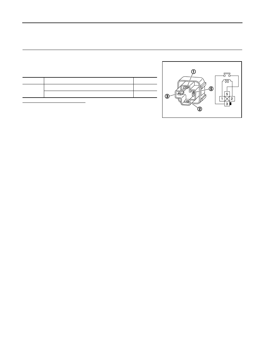
Component Inspection (Cooling Fan Relay)
INFOID:0000000005237603
1.
CHECK COOLING FAN RELAY
1.
Turn ignition switch OFF.
2.
Remove cooling fan relay.
3.
Check the continuity between cooling fan relay terminals under
the following conditions.
Is the inspection result normal?
YES
>> INSPECTION END
NO
>> Replace cooling fan relay.
Terminals
Conditions
Continuity
3 and 5
12 V direct current supply between terminals 1 and 2
Existed
No current supply
Not existed
MBIB0057E
Нет комментариевНе стесняйтесь поделиться с нами вашим ценным мнением.
Текст