Infiniti FX35, FX50 (S51). Manual — part 1519
FRONT POWER WINDOW SWITCH (PASSENGER SIDE)
PWC-137
< REMOVAL AND INSTALLATION >
[FRONT & REAR WINDOW ANTI-PINCH]
C
D
E
F
G
H
I
J
L
M
A
B
PWC
N
O
P
FRONT POWER WINDOW SWITCH (PASSENGER SIDE)
Removal and Installation
INFOID:0000000005248250
REMOVAL
1.
Remove the front door finisher.
Refer to
INT-11, "Removal and Installation"
.
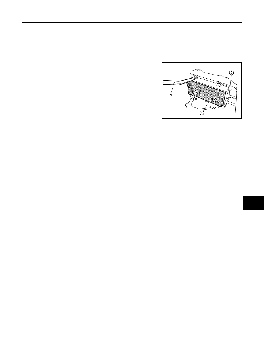
2.
Front power window switch (passenger side) (1) is removed
from front power window switch finisher (2) using flat-bladed
screw driver (A) etc.
CAUTION:
Never fold pawl of front door finisher.
INSTALLATION
Install in the reverse order of removal.
NOTE:
If front power window switch (passenger side) is replaced or is removed, it is necessary to perform the initial-
ization procedure.
JMKIA2756ZZ
PWC-138
< REMOVAL AND INSTALLATION >
[FRONT & REAR WINDOW ANTI-PINCH]
REAR POWER WINDOW SWITCH
REAR POWER WINDOW SWITCH
Removal and Installation
INFOID:0000000005248251
REMOVAL
1.
Remove the rear door finisher.
Refer to
INT-14, "Removal and Installation"
.
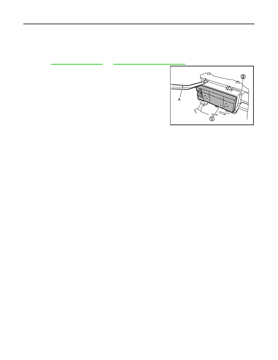
2.
Rear power window switch (1) is removed from rear power win-
dow switch finisher (2) using flat-bladed screw driver (A) etc.
CAUTION:
Never fold pawl of rear door finisher.
INSTALLATION
Install in the reverse order of removal.
NOTE:
If rear power window switch is replaced or is removed, it is necessary to perform the initialization procedure.
JMKIA2756ZZ

DIAGNOSIS AND REPAIR WORKFLOW
PWC-139
< BASIC INSPECTION >
[FRONT WINDOW ANTI-PINCH]
C
D
E
F
G
H
I
J
L
M
A
B
PWC
N
O
P
BASIC INSPECTION
DIAGNOSIS AND REPAIR WORKFLOW
Work Flow
INFOID:0000000005248252
DETAILED FLOW
1.
OBTAIN INFORMATION ABOUT SYMPTOM
Interview the customer to obtain as much malfunction information (conditions and environment when the mal-
function occurred) as possible when the customer brings the vehicle in.
>> GO TO 2.
2.
REPRODUCE THE MALFUNCTION INFORMATION
Check the malfunction on the vehicle that the customer describes.
Inspect the relation of the symptoms and the condition when the symptoms occur.
>> GO TO 3.
3.
IDENTIFY THE MALFUNCTIONING SYSTEM WITH “SYMPTOM DIAGNOSIS”
Use “Symptom diagnosis” from the symptom inspection result in step 2. Then identify where to start the diag-
nosis based on possible causes and symptoms.
>> GO TO 4.
4.
IDENTIFY MALFUNCTIONING PARTS WITH “COMPONENT DIAGNOSIS”
Perform the diagnosis with “Component diagnosis” of the applicable system.
>> GO TO 5.
5.
REPAIR OR REPLACE THE MALFUNCTIONING PARTS
Repair or replace the specified malfunctioning parts.
>> GO TO 6.
6.
FINAL CHECK
Check that malfunctions are not reproduced when obtaining the malfunction information from the customer,
referring to the symptom inspection result in step 2.
Is the malfunctioning part repaired or replaced?
YES
>> Trouble diagnosis is completed.
NO
>> GO TO 3.
PWC-140
< BASIC INSPECTION >
[FRONT WINDOW ANTI-PINCH]
INSPECTION AND ADJUSTMENT
INSPECTION AND ADJUSTMENT
ADDITIONAL SERVICE WHEN REMOVING BATTERY NEGATIVE TERMINAL
ADDITIONAL SERVICE WHEN REMOVING BATTERY NEGATIVE TERMINAL : De-
scription
INFOID:0000000005248253
When the battery negative terminal is disconnected, the initialization is necessary.
If any of the following operations are performed, the initialization is necessary as well as when the negative
terminal of battery is disconnected.
• Power supply to the power window main switch or power window motor is cut off by the removal
of battery terminal or if the battery fuse is blown.
• Disconnection and connection of power window main switch harness connector.
• Removal and installation of motor from regulator assembly.
• Operation of regulator assembly as an independent unit.
• Removal and installation of glass.
• Removal and installation of door glass run.
The following specified operations can not be performed under the non-initialized condition.
• Auto-up operation
• Anti-pinch function
ADDITIONAL SERVICE WHEN REMOVING BATTERY NEGATIVE TERMINAL : Spe-
cial Repair Requirement
INFOID:0000000005248254
INITIALIZATION PROCEDURE
1.
Disconnect the battery negative terminal or power window main switch connector. Reconnect it after a
minute or more.
2.
Turn ignition switch ON.
3.
Operate power window switch to fully open the window. (This operation is unnecessary if the window is
already fully open)
4.
Continue pulling the power window switch UP (AUTO-UP operation). Even after glass stops at the fully
closed position, keep pulling the switch for 3 seconds or more.
5.
Initializing procedure is completed.
6.
Inspect anti-pinch function.
CHECK ANTI-PINCH FUNCTION
1.
Fully open the door window.
2.
Place a piece of wood near fully closed position.
3.
Close door glass completely with AUTO-UP.
• Check that glass lowers for approximately 150 mm (5.9 in) or for 2 seconds without pinching piece of wood
and stops.
• Check that glass does not rise when operating the power window main switch while lowering.
CAUTION:
• Perform initial setting when auto-up operation or anti-pinch function does not operate normally.
• Check that AUTO-UP operates before inspection when system initialization is performed.
• Never check with hands or other body parts because they may be pinched. Never get pinched.
• It may switch to fail-safe mode if open/close operation is performed continuously without fully clos-
ing. Perform initial setting in that situation. Refer to
• Finish initial setting. Otherwise, next operation cannot be done.
1.
Auto-up operation
2.
Anti-pinch function
ADDITIONAL SERVICE WHEN REPLACING CONTROL UNIT
ADDITIONAL SERVICE WHEN REPLACING CONTROL UNIT : Description
INFOID:0000000005248255
When the control unit replaced, the initialization in necessary.
If any of the following operations are performed, the initialization is necessary as well as when the control unit
is disconnected.
• Power supply to the power window main switch or power window motor is cut off by the removal
of battery terminal or if the battery fuse is blown.
Нет комментариевНе стесняйтесь поделиться с нами вашим ценным мнением.
Текст