Infiniti FX35, FX50 (S51). Manual — part 1887

OIL PAN
TM-355
< REMOVAL AND INSTALLATION >
[7AT: RE7R01B (VK50VE)]
C
E
F
G
H
I
J
K
L
M
A
B
TM
N
O
P
OIL PAN
Exploded View
INFOID:0000000005250356
Removal and Installation
INFOID:0000000005250357
REMOVAL
1.
Drain ATF through drain plug.
2.
Disconnect heated oxygen sensor 2 connectors (A).
3.
Remove heated oxygen sensor 2 harness (B) from clips (1).
4.
Remove bracket (2) from A/T assembly.
1.
A/T
2.
Oil pan gasket
3.
Oil pan
4.
Clip
5.
Oil pan mounting bolt
6.
Overflow plug
7.
Drain plug
8.
Drain plug gasket
9.
Magnet
Refer to
JPDIA0883GB
: Vehicle front
JPDIA0902ZZ
TM-356
< REMOVAL AND INSTALLATION >
[7AT: RE7R01B (VK50VE)]
OIL PAN
5.
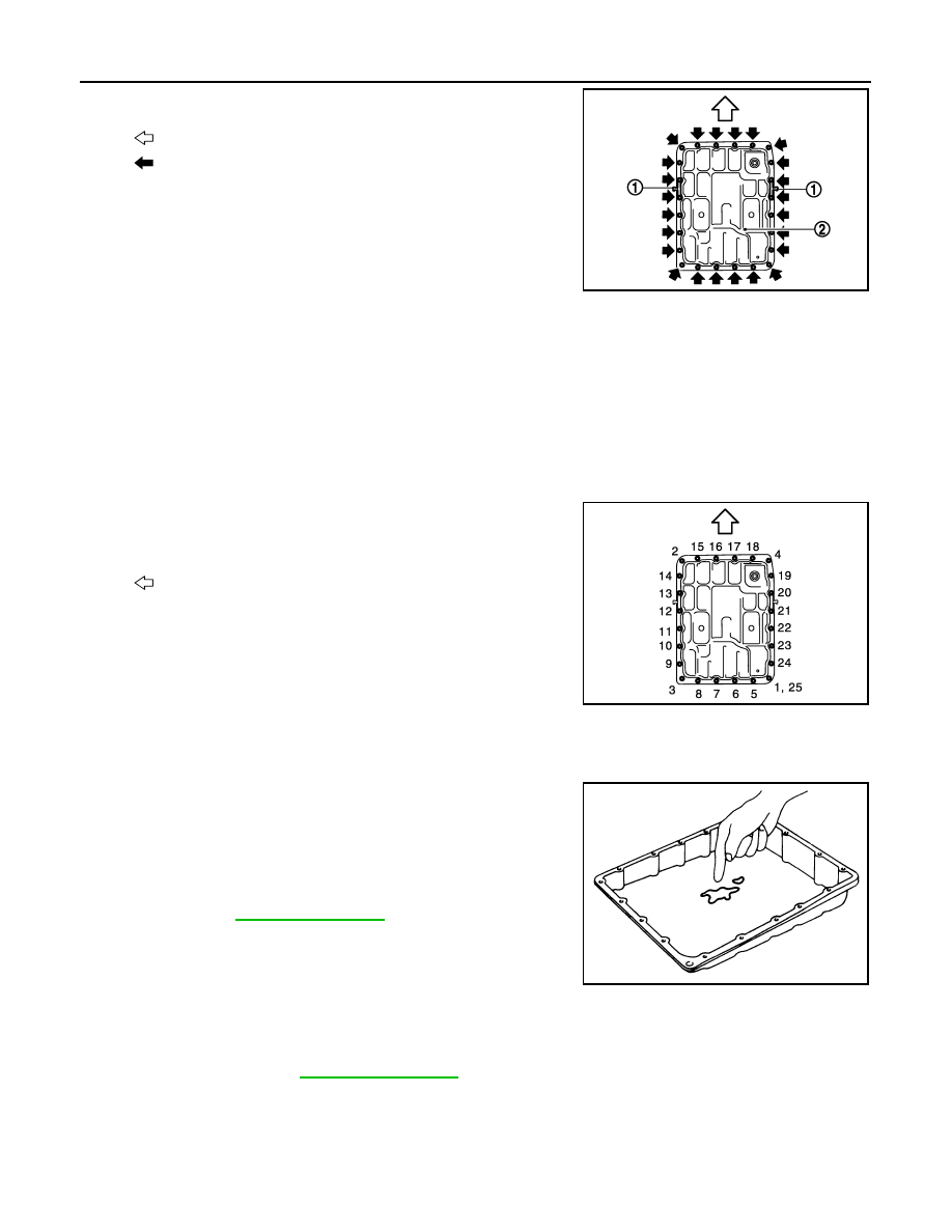
Remove clips (1).
6.
Remove oil pan (2) and oil pan gasket.
7.
Remove magnets from oil pan.
INSTALLATION
Note the following, and install in the reverse order of removal.
CAUTION:
• Clean foreign materials (gear wear particles) that adhere on the inside of the oil pan and on the mag-
net, and then assembly.
• Completely remove all moisture, oil and old gasket, etc. from oil pan gasket mounting surface of
transmission case and oil pan.
• Never reuse oil pan gasket and oil pan mounting bolts.
• Install oil pan gasket in the direction to align hole position.
• Never reuse drain plug and drain plug gasket. In addition, install new drain plug and drain plug gas-
ket after adjustment of A/T fluid filling.
• Tighten the oil pan mounting bolts to the specified torque in the
numerical order as shown in the figure after temporarily tightening
them.
Inspection and Adjustment
INFOID:0000000005250358
INSPECTION AFTER REMOVAL
Check foreign materials in oil pan to help determine causes of mal-
function. If the ATF is very dark, smells burned, or contains foreign
particles, the frictional material (clutches, band) may need replace-
ment. A tacky film that will not wipe clean indicates varnish build up.
Varnish can cause valves, servo, and clutches to stick and can
inhibit pump pressure.
• If frictional material is detected, perform A/T fluid cooler
cleaning. Refer to
.
INSPECTION AFTER INSTALLATION
Check A/T fluid leakage.
ADJUSTMENT AFTER INSTALLATION
Adjust A/T fluid level. Refer to
: Vehicle front
: Oil pan mounting bolt
JSDIA0793ZZ
: Vehicle front
JSDIA0794ZZ
SCIA5199E
AIR BREATHER HOSE
TM-357
< REMOVAL AND INSTALLATION >
[7AT: RE7R01B (VK50VE)]
C
E
F
G
H
I
J
K
L
M
A
B
TM
N
O
P
AIR BREATHER HOSE
Exploded View
INFOID:0000000005250359
Removal and Installation
INFOID:0000000005250360
REMOVAL
1.
Remove front propeller shaft. Refer to
DLN-111, "VK50VE : Exploded View"
.
2.
Remove exhaust mounting bracket and three way catalyst (right bank). Refer to
3.
Remove air breather hose.
4.
Remove rear propeller shaft. Refer to
5.
Remove control rod from A/T shift selector. Refer to
.
6.
Support A/T assembly with a transmission jack.
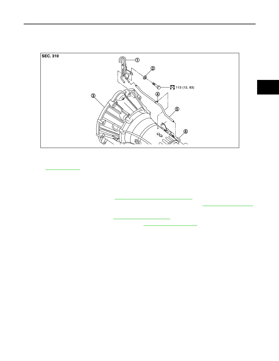
1.
Air breather vent
2.
Spring washer
3.
A/T assembly
4.
Clip
5.
Air breather hose
6.
Air breather tube
Refer to
JPDIA0866GB
TM-358
< REMOVAL AND INSTALLATION >
[7AT: RE7R01B (VK50VE)]
AIR BREATHER HOSE
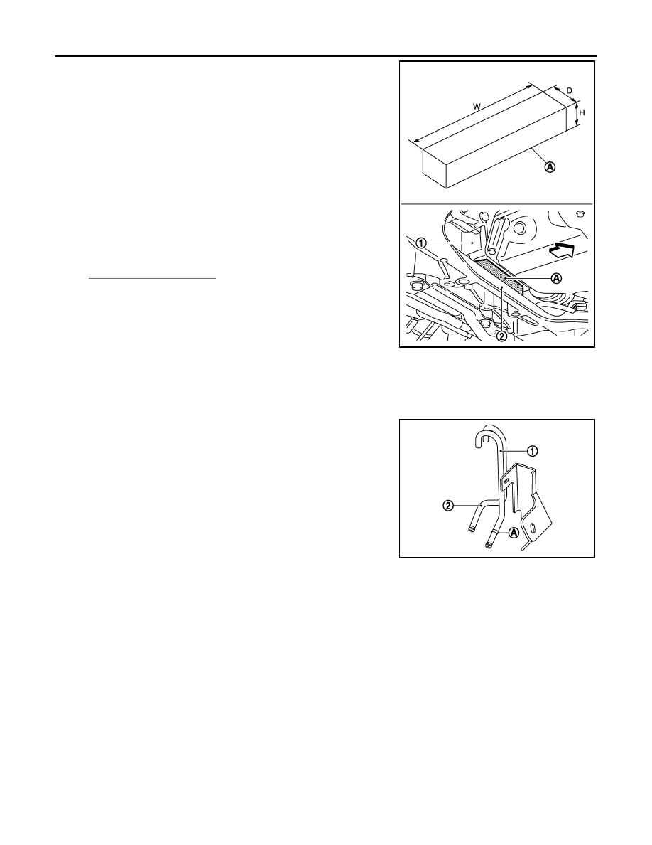
7.
Insert a wooden block (A) between oil pan (upper) (1) of engine
and front suspension member (2).
CAUTION:
• Always insert a wooden block between oil pan (upper) of
engine and front suspension member when removing air
breather vent. (Because VVEL control shaft position sen-
sor may be damaged by the interference between VVEL
control shaft position sensor and dash panel if the opera-
tion is performed without the wooden block inserted.)
• After inserting wooden block, check it does not fall out
easily.
8.
Remove rear engine mounting member with a power tool. Refer
to
9.
Remove bolt fixing A/T assembly to engine assembly with power
tool.
10. Remove air breather vent.
INSTALLATION
Note the following, and install in the reverse order of removal.
CAUTION:
• When installing air breather hose, be careful not to be crushed or blocked by folding or bending the
hose.
• When inserting air breather hose to the air breather vent (for
A/T) (1), be sure to insert it fully until its end reaches the spool
(A) portion.
• Install air breather hose to air breather vent (for A/T) so that
the paint mark is facing upward.
• Ensure clips are securely installed to brackets when installing
air breather hose to brackets.
W
: 150 mm (5.91 in)
D
: 30 mm (1.18 in)
H
: 20 mm (0.79 in)
JPDIA0923ZZ
2
: Air breather vent (for transfer)
JPDIA0867ZZ
Нет комментариевНе стесняйтесь поделиться с нами вашим ценным мнением.
Текст