Infiniti FX35, FX50 (S51). Manual — part 432
CHG
POWER GENERATION VOLTAGE VARIABLE CONTROL SYSTEM
CHG-9
< SYSTEM DESCRIPTION >
C
D
E
F
G
H
I
J
K
L
B
A
O
P
N
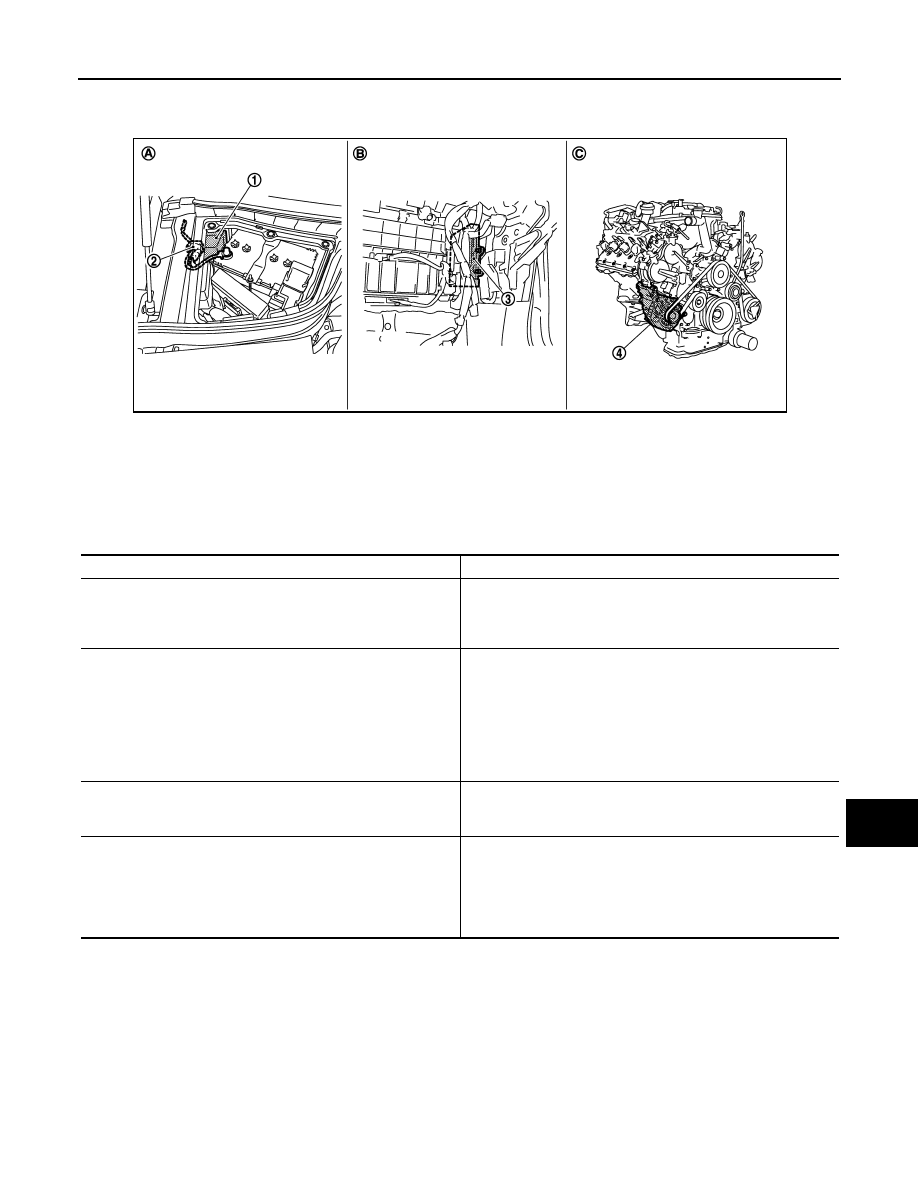
VK50VE : Component Parts Location
INFOID:0000000005242962
Component Description
INFOID:0000000005242963
1.
IPDM E/R
2.
Battery current sensor
3.
ECM
4.
Alternator
A.
Engine room dash panel (RH)
B.
Behind glove box
C.
Cylinder block (bank 1) side
JSMIA0068ZZ
Component part
Description
Battery current sensor
Battery current sensor is installed to the battery cable at the neg-
ative terminal, and it detects the charging/discharging current of
the battery and sends the voltage signal to ECM according to the
current value.
ECM
Battery current sensor detects the charging/discharging current of
the battery. ECM judges the battery condition based on this signal.
ECM judges whether to perform the power generation voltage
variable control according to the battery condition.
When performing the power generation voltage variable control,
ECM calculates the target power generation voltage according to
the battery condition and sends the calculated value as the power
generation command value to IPDM E/R.
IPDM E/R
IPDM E/R converts the received power generation command val-
ue into the power generation command signal (PWM signal) and
sends it to the IC voltage regulator.
Alternator (IC voltage regulator)
IC voltage regulator controls the power generation voltage by the
target power generation voltage based on the received power gen-
eration command signal.
When there is no power generation command signal, the alterna-
tor performs the normal power generation according to the char-
acteristic of the IC voltage regulator.
CHG-10
< DTC/CIRCUIT DIAGNOSIS >
B TERMINAL CIRCUIT
DTC/CIRCUIT DIAGNOSIS
B TERMINAL CIRCUIT
Description
INFOID:0000000005242964
“B” terminal circuit supplies power to charge the battery and to operate the vehicle’s electrical system.
Diagnosis Procedure
INFOID:0000000005242965
1.
CHECK “B” TERMINAL CONNECTION
1.
Turn ignition switch OFF.
2.
Check if “B” terminal is clean and tight.
Is the inspection result normal?
YES
>> GO TO 2.
NO
>> Repair “B” terminal connection. Confirm repair by performing complete Starting/Charging system
test. Refer to Technical Service Bulletin.
2.
CHECK “B” TERMINAL CIRCUIT
Check voltage between alternator “B” terminal and ground.
Is the inspection result normal?
YES
>> GO TO 3.
NO
>> Check harness for open between alternator and fusible link.
3.
CHECK “B” TERMINAL CONNECTION (VOLTAGE DROP TEST)
1.
Start engine, then engine running at idle and warm.
2.
Check voltage between battery positive terminal and alternator “B” terminal.
Is the inspection result normal?
YES
>> “B” terminal circuit is normal. Refer to
.
NO
>> Check harness between battery and alternator for poor continuity.
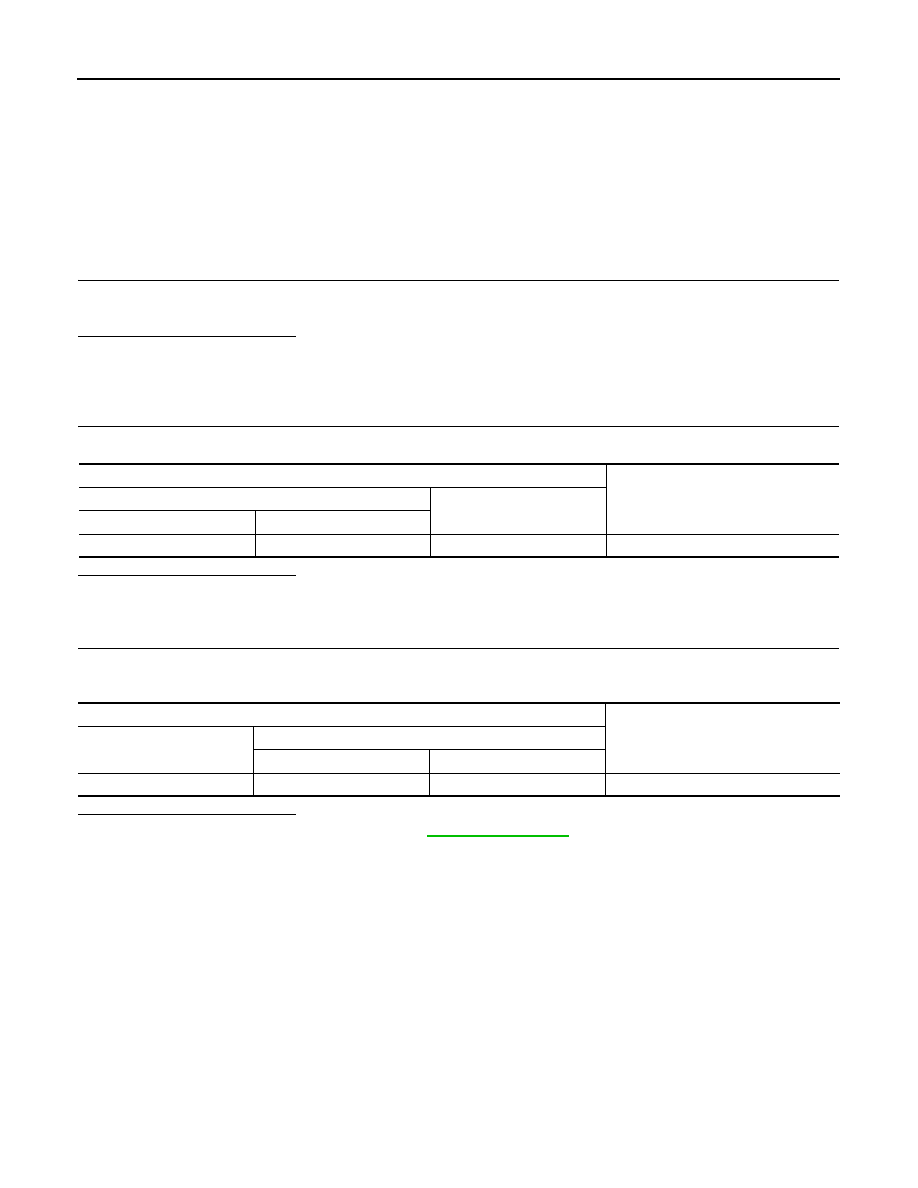
Terminals
Voltage (Approx.)
(+)
(–)
Alternator “B” terminal
Terminal
E203
1
Ground
Battery voltage
Terminals
Voltage (Approx.)
(+)
(–)
Alternator “B” terminal
Terminal
Battery positive terminal
E203
1
Less than 0.2 V
CHG
L TERMINAL CIRCUIT (OPEN)
CHG-11
< DTC/CIRCUIT DIAGNOSIS >
C
D
E
F
G
H
I
J
K
L
B
A
O
P
N
L TERMINAL CIRCUIT (OPEN)
Description
INFOID:0000000005242966
The “L” terminal circuit controls the charge warning lamp. The charge warning lamp illuminates when the igni-
tion switch is set to ON or START. When the alternator is providing sufficient voltage with the engine running,
the charge warning lamp will go off. If the charge warning lamp illuminates with the engine running, a malfunc-
tion is indicated.
Diagnosis Procedure
INFOID:0000000005242967
1.
CHECK “L” TERMINAL CONNECTION
1.
Turn ignition switch OFF.
2.
Check if “L” terminal is clean and tight.
Is the inspection result normal?
YES
>> GO TO 2.
NO
>> Repair “L” terminal connection. Confirm repair by performing complete Starting/Charging system
test. Refer to Technical Service Bulletin.
2.
CHECK “L” TERMINAL CIRCUIT (OPEN)
1.
Disconnect alternator connector.
2.
Apply ground to alternator harness connector terminal.
3.
Check condition of the charge warning lamp with the ignition switch in the ON position.
Does it illuminate?
YES
>> “L” terminal circuit is normal. Refer to
NO
>> GO TO 3.
3.
CHECK HARNESS CONTINUITY (OPEN CIRCUIT)
1.
Disconnect the battery cable from the negative terminal.
2.
Disconnect the combination meter connector.
3.
Check continuity between alternator harness connector and combination meter harness connector.
Is the inspection result normal?
YES
>> GO TO 4.
NO
>> Repair the harness or connector.
4.
CHECK HARNESS CONTINUITY (OPEN CIRCUIT)
Check continuity between combination meter harness connector and fuse block.
Is the inspection result normal?
YES
>> GO TO 5.
NO
>> Repair the harness.
5.
CHECK POWER SUPPLY CIRCUIT
1.
Connect the battery cable to the negative terminal.
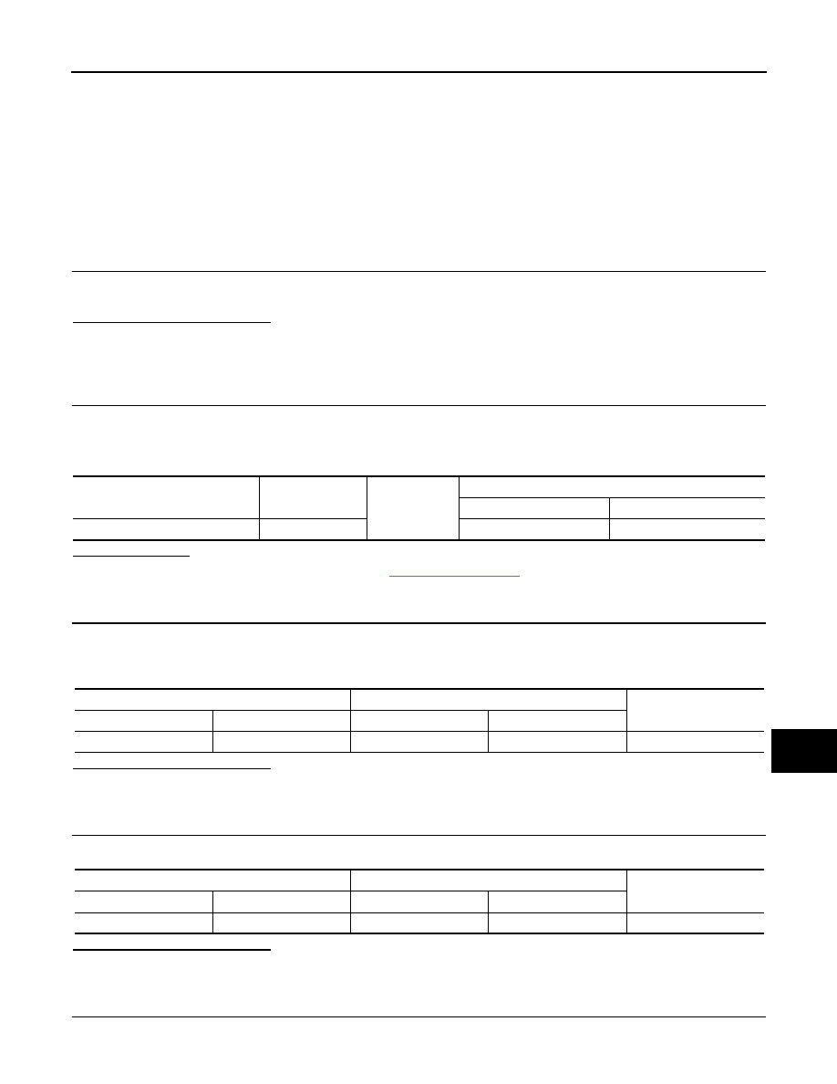
Alternator harness connector
Terminal
Ground
Condition
Ignition switch position
Charge warning lamp
F36
2
ON
Illuminate
Alternator harness connector
Combination meter harness connector
Continuity
Connector No.
Terminal No.
Connector No.
Terminal No.
F36
2
M53
6
Existed
Combination meter harness connector
Fuse block
Continuity
Connector No.
Terminal No.
Connector No.
Terminal No.
M53
21
M3
12C
Existed

CHG-12
< DTC/CIRCUIT DIAGNOSIS >
L TERMINAL CIRCUIT (OPEN)
2.
Check voltage between combination meter harness connector and ground.
Is the inspection result normal?
YES
>> Replace combination meter.
NO
>> Inspect the power supply circuit. Refer to
PG-81, "Wiring Diagram - IGNITION POWER SUPPLY -
Terminals
Condition
Voltage (Approx.)
(+)
(–)
Combination meter
harness connector
Terminal
M53
21
Ground
When the ignition switch is in
ON position
Battery voltage
Нет комментариевНе стесняйтесь поделиться с нами вашим ценным мнением.
Текст