Infiniti FX35, FX50 (S51). Manual — part 431

CHG
DIAGNOSIS AND REPAIR WORKFLOW
CHG-5
< BASIC INSPECTION >
C
D
E
F
G
H
I
J
K
L
B
A
O
P
N
8.
“S” TERMINAL CIRCUIT INSPECTION
Check “S” terminal circuit. Refer to
Is the “S” terminal circuit normal?
YES
>> GO TO 10.
NO
>> Repair as needed.
9.
INSPECTION WITH CHARGE WARNING LAMP (ENGINE AT 3,000 RPM)
Increase and maintain the engine speed at 3,000 rpm.
Does the charge warning lamp remain off?
YES
>> GO TO 11.
NO
>> GO TO 10.
10.
INSPECTION OF ALTERNATOR PULLEY
Check alternator pulley. Refer to
(VQ35HR) or
(VK50VE).
Is alternator pulley normal?
YES
>> Replace alternator.
NO
>> Repair as needed.
11.
“B” TERMINAL CIRCUIT INSPECTION
Check “B” terminal circuit. Refer to
Is “B” terminal circuit normal?
YES
>> Replace alternator.
NO
>> Repair as needed.
12.
“B” TERMINAL CIRCUIT INSPECTION
Check “B” terminal circuit. Refer to
Is “B” terminal circuit normal?
YES
>> GO TO 13.
NO
>> Repair as needed.
13.
INSPECTION OF ALTERNATOR PULLEY
Check alternator pulley. Refer to
(VQ35HR) or
(VK50VE).
Is alternator pulley normal?
YES
>> Replace alternator.
NO
>> Repair as needed.
14.
“S” TERMINAL CIRCUIT INSPECTION
Check “S” terminal circuit. Refer to
Is the “S” terminal circuit normal?
YES
>> Replace alternator.
NO
>> Repair as needed.
CHG-6
< SYSTEM DESCRIPTION >
CHARGING SYSTEM
SYSTEM DESCRIPTION
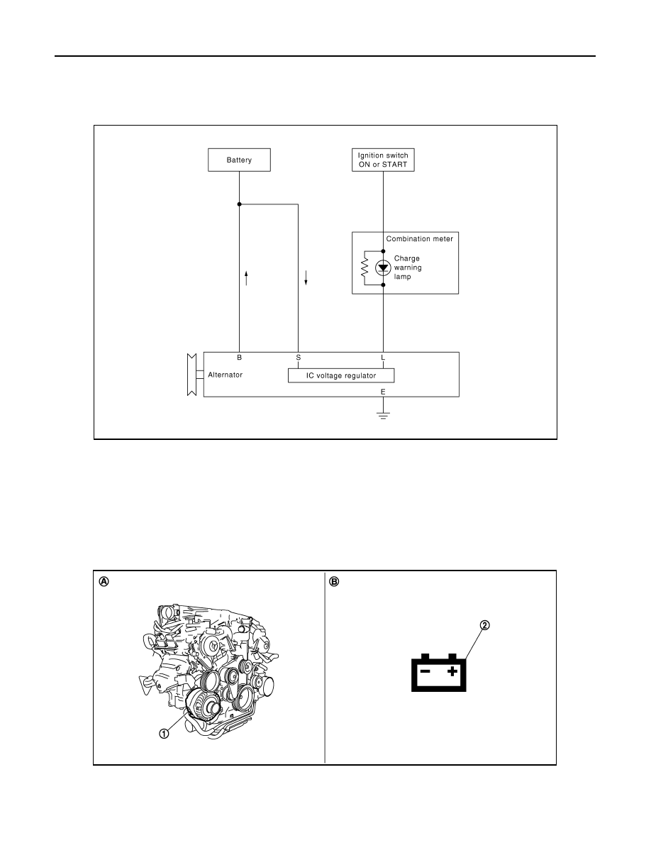
CHARGING SYSTEM
System Diagram
INFOID:0000000005242954
System Description
INFOID:0000000005242955
The alternator provides DC voltage to operate the vehicle's electrical system and to keep the battery charged.
The voltage output is controlled by the IC voltage regulator.
VQ35HR
VQ35HR : Component Parts Location
INFOID:0000000005242956
JPMIA0426GB
1.
Alternator
2.
Charge warning lamp
A.
Cylinder block (bank 1) side
B.
Combination meter
JSMIA0054ZZ
CHG
CHARGING SYSTEM
CHG-7
< SYSTEM DESCRIPTION >
C
D
E
F
G
H
I
J
K
L
B
A
O
P
N
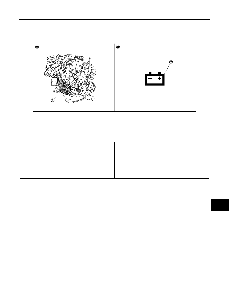
VK50VE
VK50VE : Component Parts Location
INFOID:0000000005242957
Component Description
INFOID:0000000005242958
1.
Alternator
2.
Charge warning lamp
A.
Cylinder block (bank 1) side
B.
Combination meter
JSMIA0070ZZ
Component part
Description
Alternator
The alternator provides DC voltage to operate the vehicle electri-
cal system and to keep the battery charged.
Combination meter (Charge warning lamp)
The IC voltage regulator warning function activates to illuminate
the charge warning lamp, if any of the following symptoms occur
while alternator is operating:
• Excessive voltage is produced.
• No voltage is produced.
CHG-8
< SYSTEM DESCRIPTION >
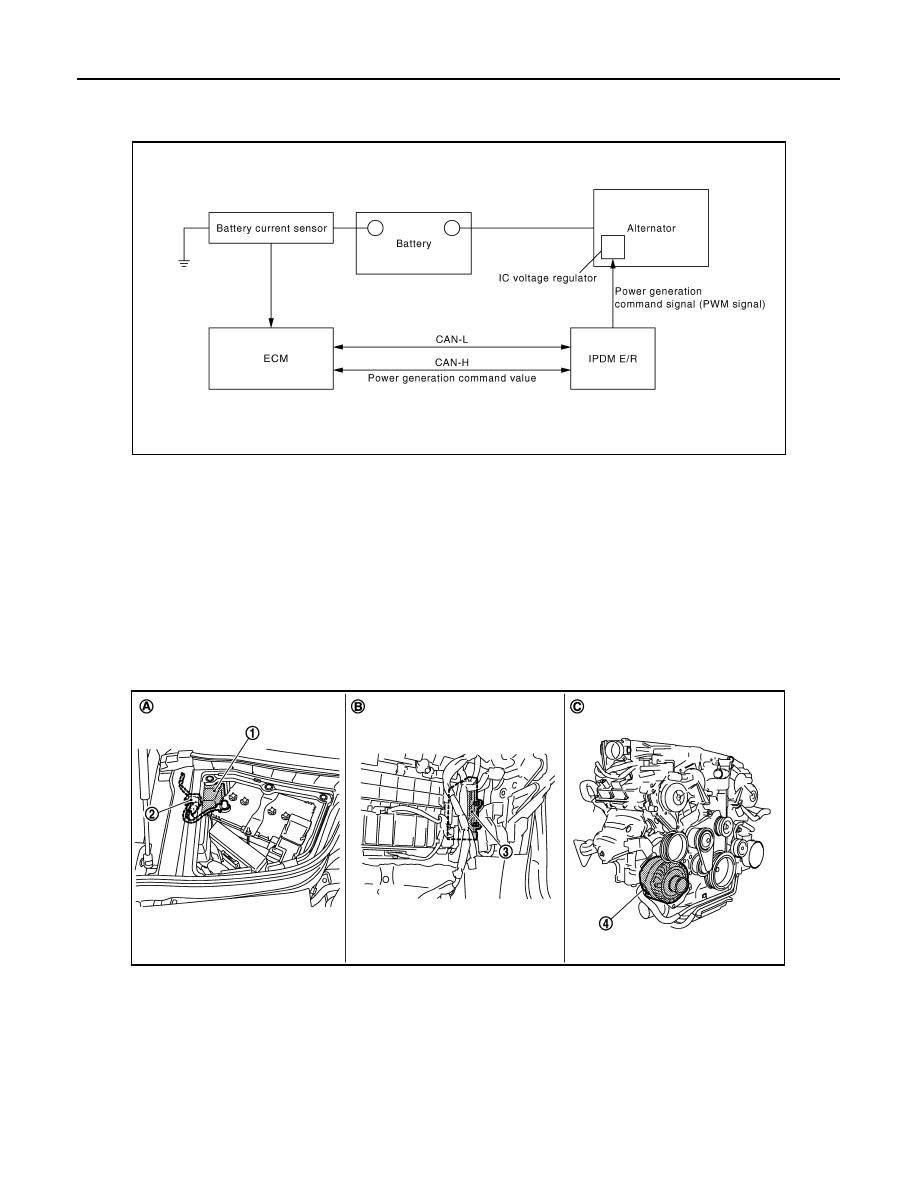
POWER GENERATION VOLTAGE VARIABLE CONTROL SYSTEM
POWER GENERATION VOLTAGE VARIABLE CONTROL SYSTEM
System Diagram
INFOID:0000000005242959
System Description
INFOID:0000000005242960
By performing the power generation voltage variable control, the engine load due to the power generation of
the alternator is reduced and fuel consumption is decreased.
NOTE:
When any malfunction is detected in the power generation voltage variable control system, the power genera-
tion is performed according to the characteristic of the IC voltage regulator of the alternator.
VQ35HR
VQ35HR : Component Parts Location
INFOID:0000000005242961
VK50VE
JPMIA0632GB
1.
IPDM E/R
2.
Battery current sensor
3.
ECM
4.
Alternator
A.
Engine room dash panel (RH)
B.
Behind glove box
C.
Cylinder block (bank 1) side
JSMIA0069ZZ
Нет комментариевНе стесняйтесь поделиться с нами вашим ценным мнением.
Текст