Infiniti FX35, FX50 (S51). Manual — part 449
RADIATOR
CO-41
< REMOVAL AND INSTALLATION >
[VK50VE]
C
D
E
F
G
H
I
J
K
L
M
A
CO
N
P
O
b.
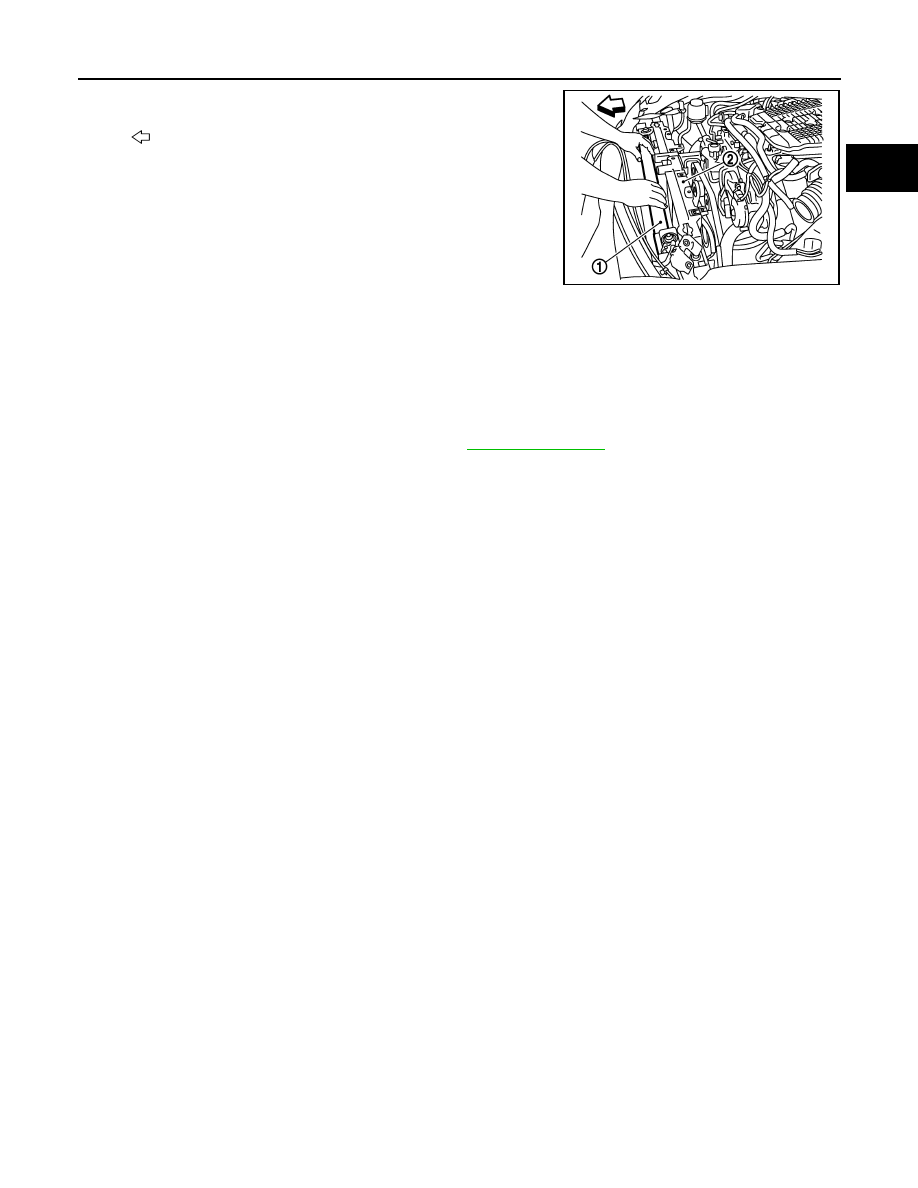
Remove radiator (1) from front of radiator core support (2).
INSTALLATION
Installation is the reverse order of removal.
Inspection
INFOID:0000000005246392
INSPECTION AFTER INSTALLATION
• Check for leakage of engine coolant using the radiator cap tester adapter (commercial service tool) and the
radiator cap tester (commercial service tool). Refer to
• Start and warm up the engine. Visually check that there is no leakage of engine coolant and A/T fluid.
: Vehicle front
JPBIA0107ZZ
CO-42
< REMOVAL AND INSTALLATION >
[VK50VE]
COOLING FAN
COOLING FAN
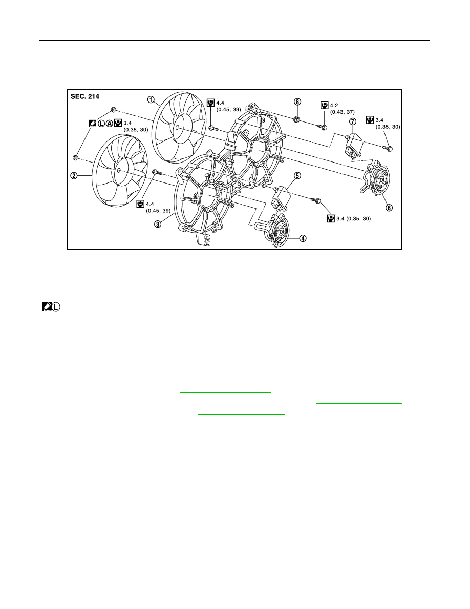
Exploded View
INFOID:0000000005246393
Removal and Installation
INFOID:0000000005246394
REMOVAL
1.
Drain engine coolant. Refer to
2.
Remove reservoir tank. Refer to
.
3.
Remove air cleaner case. Refer to
.
4.
Remove mounting bolt from high pressure flexible hose bracket. Refer to
5.
Remove radiator hose (upper). Refer to
.
6.
Disconnect harness connector from cooling fan control modules, and move harness to aside.
7.
Remove cooling fan assembly.
CAUTION:
Be careful not to damage or scratch on radiator core.
INSTALLATION
Note the following, and install in the reverse order of removal.
CAUTION:
Only use genuine parts for cooling fan mounting bolt and observe the specified torque (to prevent
radiator from being damaged).
Disassembly and Assembly
INFOID:0000000005246395
DISASSEMBLY
1.
Disconnect harness connector from cooling fan control modules.
2.
Remove cooling fan control modules from cooling fan assembly.
CAUTION:
Handle carefully to avoid dropping and impact.
1.
Cooling fan (RH)
2.
Cooling fan (LH)
3.
Fan shroud
4.
Fan motor (LH)
5.
Cooling fan control module
6.
Fan motor (RH)
7.
Cooling fan control module
8.
Grommet
A.
Apply on fan motor shaft
: Apply high strength thread locking sealant or equivalent.
Refer to
for symbols not described on the above.
JPBIA2342GB
COOLING FAN
CO-43
< REMOVAL AND INSTALLATION >
[VK50VE]
C
D
E
F
G
H
I
J
K
L
M
A
CO
N
P
O
3.
Remove cooling fan mounting nuts, and then remove the cooling fan (RH and LH).
4.
Remove fan motors (RH and LH).
ASSEMBLY
Note the following, and assemble in the reverse order of disassembly.
CAUTION:
RH and LH cooling fans are different. Be careful not to misassemble them.
• Install each fan in the following position.
• Secure the harness tightly to the fan shroud to prevent the fan rotation area from being slack.
Inspection
INFOID:0000000005246396
INSPECTION AFTER REMOVAL
Check that fan motors operate normally.
NOTE:
Cooling fans are controlled by cooling fan control module. For details, refer to
.
INSPECTION AFTER DISASSEMBLY
Cooling Fan
Inspect cooling fan for crack or unusual bend.
• If anything is found, replace cooling fan.
Right side
: 9 blades
Left side
: 11 blades

CO-44
< REMOVAL AND INSTALLATION >
[VK50VE]
WATER PUMP
WATER PUMP
Exploded View
INFOID:0000000005246397
Removal and Installation
INFOID:0000000005246398
CAUTION:
• When removing water pump assembly, be careful not to get engine coolant on drive belts.
• Water pump cannot be disassembled and should be replaced as a unit.
• After installing water pump, connect hose and clamp securely, then check for leakage using the radi-
ator cap tester (commercial service tool) and the radiator cap tester adapter (commercial service
tool).
REMOVAL
1.
Remove following parts:
• Engine undercover, using a power tool.
• Engine cover and engine room cover (RH and LH). Refer to
.
• Air duct (inlet): Refer to
• Reservoir tank. Refer to
.
2.
Loosen water pump pulley mounting bolts.
3.
Remove alternator, water pump and A/C compressor belt: Refer to
EM-164, "Removal and Installation"
4.
Remove water pump pulley.
5.
Drain engine coolant from drain plugs on radiator and cylinder block. Refer to
CAUTION:
• Perform this step when engine is cold.
• Never spill engine coolant on drive belt.
6.
Remove water pump. Refer to
.
• Engine coolant will leak from cylinder block, so have a receptacle ready under vehicle.
1.
Water pump pulley
2.
Water pump
3.
Gasket
Refer to
for symbols in the figure.
JPBIA2316GB
Нет комментариевНе стесняйтесь поделиться с нами вашим ценным мнением.
Текст