Infiniti FX35, FX50 (S51). Manual — part 448
RADIATOR
CO-37
< PERIODIC MAINTENANCE >
[VK50VE]
C
D
E
F
G
H
I
J
K
L
M
A
CO
N
P
O
RADIATOR
RADIATOR CAP
RADIATOR CAP : Inspection
INFOID:0000000005246388
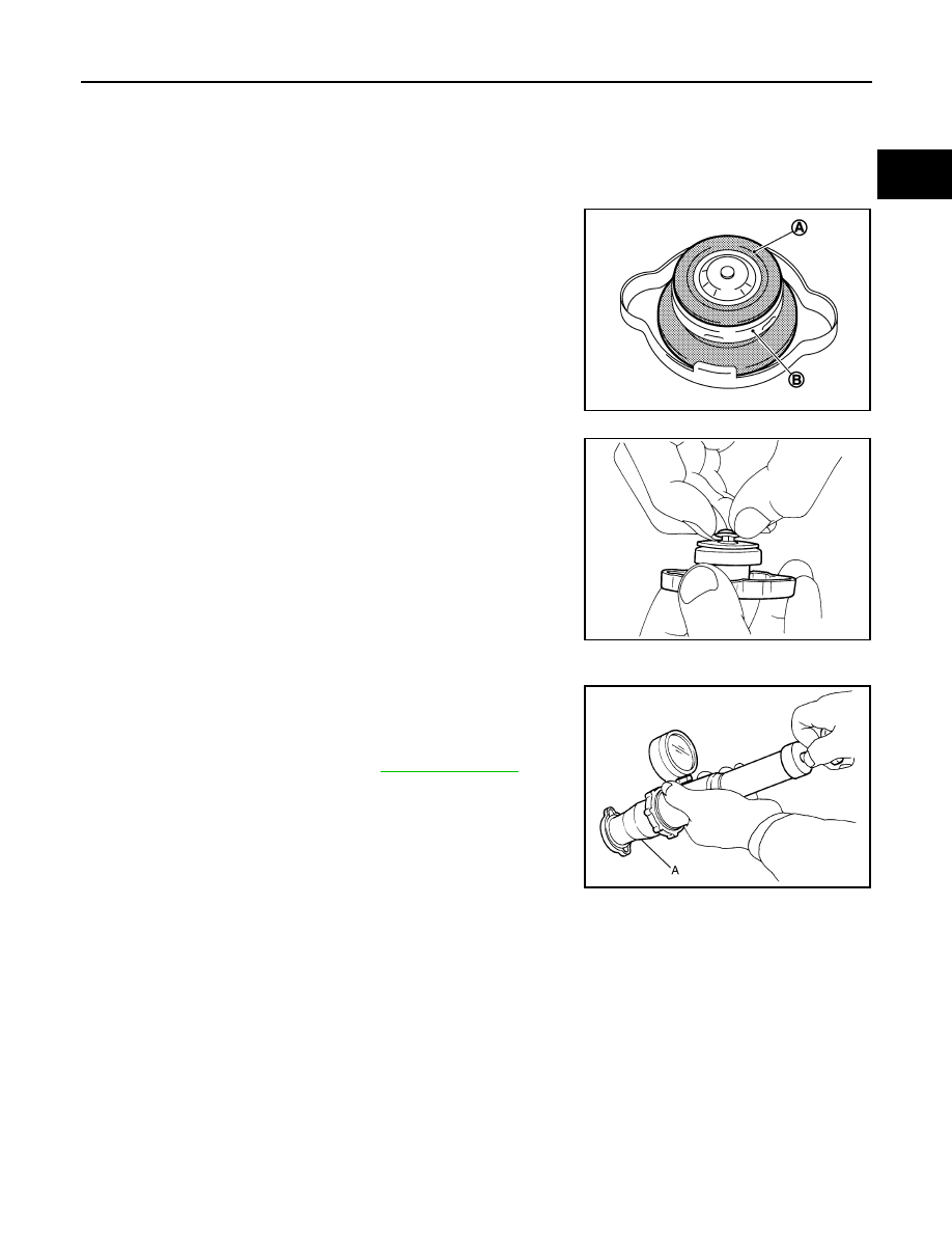
• Check valve seat of radiator cap.
- Check if valve seat (A) is swollen to the extent that the edge of the
metal plunger (B) cannot be seen when watching it vertically from
the top.
- Check if valve seat has no soil and damage.
• Pull negative-pressure valve to open it, and check that it close
completely when released.
- Check that there is no dirt or damage on the valve seat of radiator
cap negative-pressure valve.
- Check that there are no unusualness in the opening and closing
conditions of negative-pressure valve.
• Check radiator cap relief pressure.
- When connecting radiator cap to the radiator cap tester (commer-
cial service tool) and the radiator cap tester adapter (commercial
service tool) (A), apply engine coolant to the cap seal surface.
• Replace radiator cap if there is an unusualness related to the above three.
CAUTION:
When installing radiator cap, thoroughly wipe out the water inlet filler neck to remove any waxy resi-
due or foreign material.
RADIATOR
RADIATOR : Inspection
INFOID:0000000005246389
Check radiator for mud or clogging. If necessary, clean radiator as per the following:
• Be careful not to bend or damage radiator fins.
• When radiator is cleaned without removal, remove all surrounding parts such as radiator cooling fan assem-
bly and horns. Then tape harness and connectors to prevent water from entering.
1.
Apply water by hose to the back side of the radiator core vertically downward.
2.
Apply water again to all radiator core surfaces once per minute.
JPBIA0108ZZ
SMA967B
Standard and limit
: Refer to
.
JPBIA0109ZZ
CO-38
< PERIODIC MAINTENANCE >
[VK50VE]
RADIATOR
3.
Stop washing if any stains no longer flow out from radiator.
4.
Blow air into the back side of radiator core vertically downward.
• Use compressed air lower than 490 kPa (5 kg/cm
2
, 71 psi) and keep distance more than 30 cm (11.8 in).
5.
Blow air again into all the radiator core surfaces once per minute until no water sprays out.
RADIATOR
CO-39
< REMOVAL AND INSTALLATION >
[VK50VE]
C
D
E
F
G
H
I
J
K
L
M
A
CO
N
P
O
REMOVAL AND INSTALLATION
RADIATOR
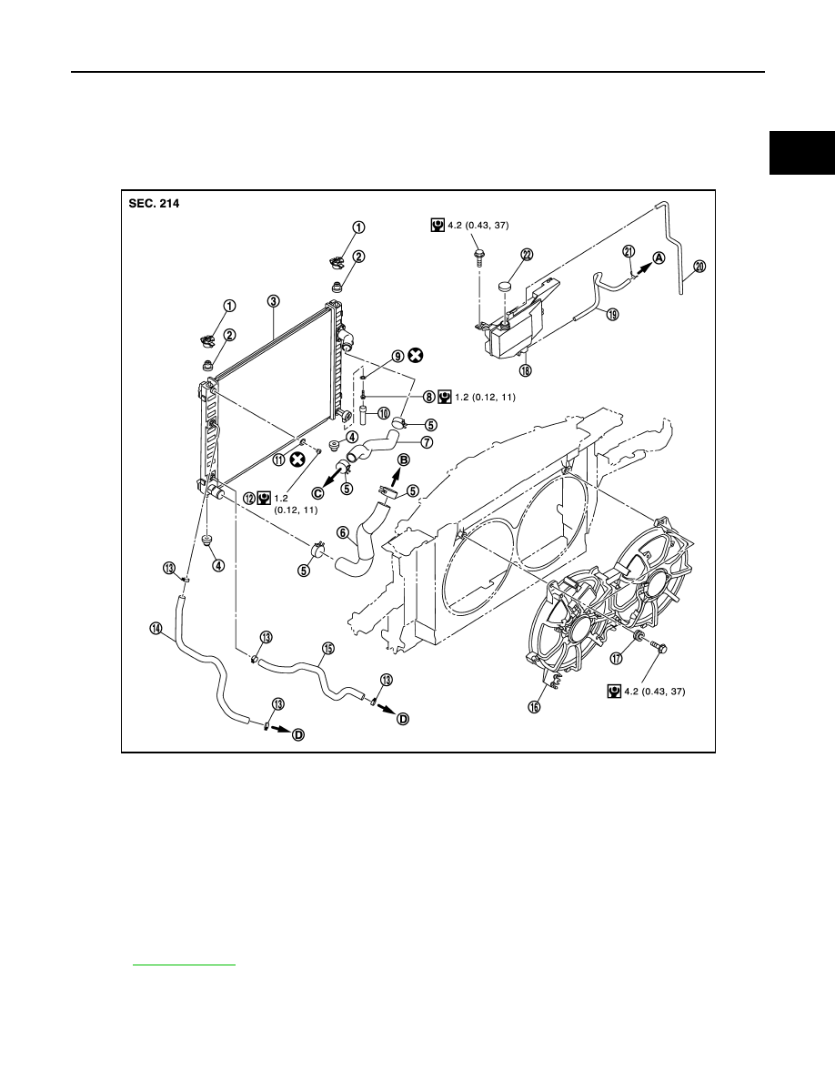
Exploded View
INFOID:0000000005246390
Removal and Installation
INFOID:0000000005246391
REMOVAL
1.
Upper mount bracket
2.
Mounting rubber (upper)
3.
Radiator
4.
Mounting rubber (lower)
5.
Clamp
6.
Radiator hose (lower)
7.
Radiator hose (upper)
8.
Drain plug
9.
O-ring
10. Water drain hose
11.
O-ring
12. Air relief plug
13. Clamp
14. A/T fluid cooler hose
15. A/T fluid cooler hose
16. Cooling fan assembly
17. Grommet
18. Reservoir tank
19. Reservoir tank hose
20. Reservoir tank hose
21. Clamp
22. Reservoir tank cap
A.
To water inlet (inlet side)
B.
To water suction pipe
C.
To water inlet (outlet side)
D.
To A/T fluid cooler pipe
Refer to
for symbols in the figure.
JPBIA2317GB
CO-40
< REMOVAL AND INSTALLATION >
[VK50VE]
RADIATOR
WARNING:
Never remove radiator cap when engine is hot. Serious burns could occur from high-pressure engine
coolant escaping from water inlet. Wrap a thick cloth around the cap. Slowly turn it a quarter of a turn
to release built-up pressure. Carefully remove radiator cap by turning it all the way.
1.
Remove the following parts:
• Engine under cover, using a power tool.
• Engine cover and engine room cover (RH and LH): Refer to
.
• Air cleaner case: Refer to
• Air duct (inlet): Refer to
• Hood lock stay assembly and horn: Refer to
.
2.
Remove condenser. Refer to
3.
Drain engine coolant from radiator. Refer to
.
CAUTION:
• Perform this step when the engine is cold.
• Never spill engine coolant on drive belts.
4.
Disconnect A/T fluid cooler hoses from radiator.
• Install blind plug to avoid leakage of A/T fluid.
5.
Remove radiator hoses (upper and lower) and reservoir tank hose.
CAUTION:
• Be careful not to allow engine coolant to contact drive belts.
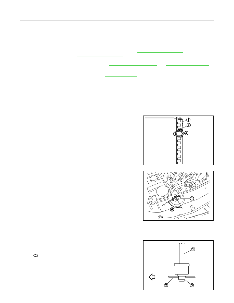
• Never loosen radiator water inlet pipe mounting screw
(A). If loosened, replace radiator (1).
6.
Rotate two radiator upper mount brackets 90 degrees in direc-
tion as shown in the figure, and remove them.
7.
Remove radiator as per the following:
CAUTION:
Be careful not to damage radiator core.
a.
Lift up and pull the radiator (1) forward, and then remove the
mounting rubber (lower) (3) from the radiator core support (2).
2
: Radiator water inlet pipe
JPBIA1832ZZ
1
: Radiator upper mount bracket
A
: Turn 90
°
counterclockwise
JPBIA0105ZZ
: Vehicle front
JPBIA0106ZZ
Нет комментариевНе стесняйтесь поделиться с нами вашим ценным мнением.
Текст