Infiniti FX35, FX50 (S51). Manual — part 450
WATER PUMP
CO-45
< REMOVAL AND INSTALLATION >
[VK50VE]
C
D
E
F
G
H
I
J
K
L
M
A
CO
N
P
O
CAUTION:
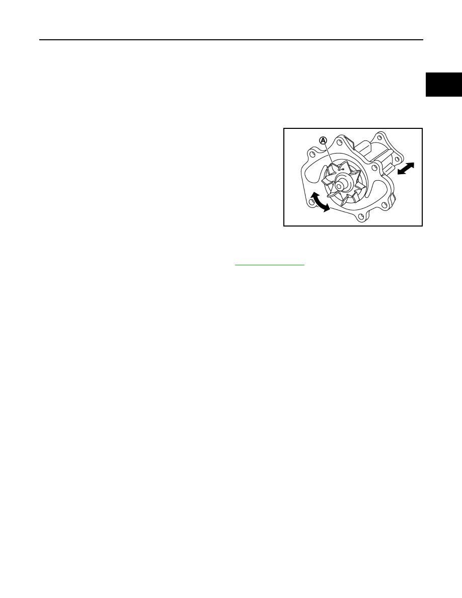
• Handle the water pump vane so that it does not contact any other parts.
• Never disassemble water pump.
INSTALLATION
Install in the reverse order of removal.
Inspection
INFOID:0000000005246399
INSPECTION AFTER REMOVAL
• Visually check that there is no significant dirt or rusting on water
pump body and vane (A).
• Check there is no slack in vane shaft, and that it turns smoothly
when rotated by hand.
• If anything is found, replace water pump.
INSPECTION AFTER INSTALLATION
• Check that the reservoir tank cap is tightened.
• Check for leakage of engine coolant using the radiator cap tester adapter (commercial service tool) and the
radiator cap tester (commercial service tool). Refer to
• Start and warm up the engine. Visually check that there is no leakage of engine coolant.
JPBIA2315ZZ
CO-46
< REMOVAL AND INSTALLATION >
[VK50VE]
WATER INLET AND THERMOSTAT ASSEMBLY
WATER INLET AND THERMOSTAT ASSEMBLY
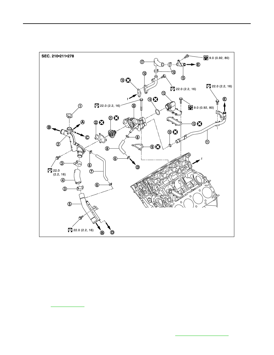
Exploded View
INFOID:0000000005246400
Removal and Installation
INFOID:0000000005246401
REMOVAL
1.
Remove engine cover and engine room cover (RH and LH). Refer to
1.
Radiator cap
2.
Water inlet
3.
Clamp
4.
Water suction hose
5.
Water suction pipe
6.
Clamp
7.
Water hose
8.
Water hose
9.
Gasket
10. O-ring
11.
Heater pipe
12.
Gasket
13. Water connector
14. O-ring
15.
Water pipe
16. Clamp
17. Water hose
18.
Water pipe
19. Gasket
20. Thermostat housing
21.
Thermostat
22. Gasket
A.
To electric throttle control actuator
B.
To radiator
C.
To reservoir tank
D.
To oil cooler
E.
To heater
Refer to
for symbols in the figure.
JPBIA2318GB
WATER INLET AND THERMOSTAT ASSEMBLY
CO-47
< REMOVAL AND INSTALLATION >
[VK50VE]
C
D
E
F
G
H
I
J
K
L
M
A
CO
N
P
O
2.
Remove air duct (inlet). Refer to
.
3.
Remove reservoir tank. Refer to
.
4.
Remove engine undercover with a power tool.
5.
Drain engine coolant from drain plugs on radiator and cylinder block. Refer to
CAUTION:
• Perform this step when engine is cold.
• Never spill engine coolant on drive belts.
6.
Disconnect radiator hose (upper and lower). Refer to
7.
Remove intake manifold. Refer to
8.
Remove water suction pipe and water suction hose.
9.
Remove water inlet and thermostat.
10. Remove water connector, heater pipes and heater hoses.
11. Remove thermostat housing.
INSTALLATION
Note the following, and install in the reverse order of removal.
CAUTION:
Be careful not to spill engine coolant over engine room. Use rag to absorb engine coolant.
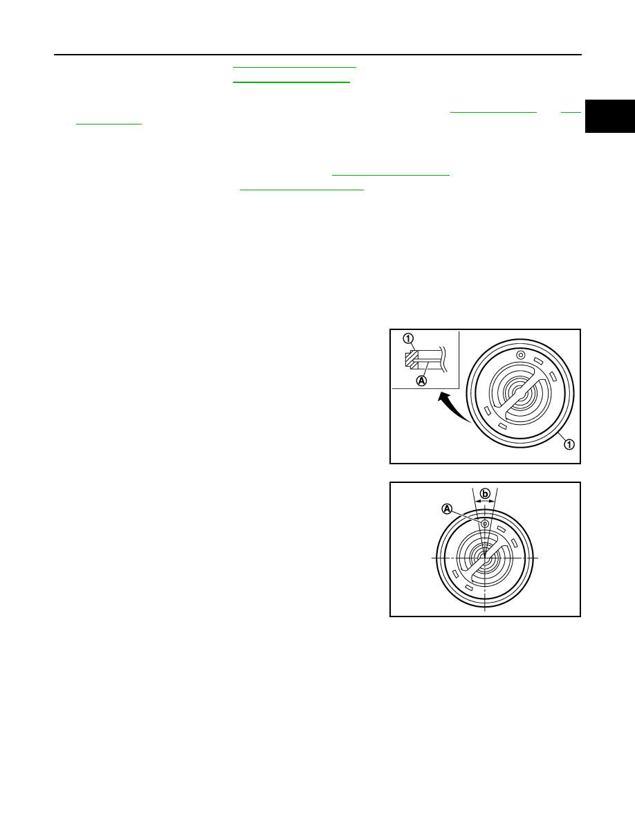
Thermostat
• Install thermostat with the whole circumference of each flange part
(A) fit securely inside rubber ring (1).
• Install thermostat with jiggle valve (A) facing upwards. The position
deviation may be within the range of 20 degrees (b).
Water Connector and Heater Pipe
• First apply a neutral detergent to O-rings, then quickly insert the insertion parts of the water connector and
heater pipe into the installation holes.
Inspection
INFOID:0000000005246402
INSPECTION AFTER REMOVAL
• Check that valve in thermostat is completely closing at normal temperature.
PBIC3315J
JPBIA2314ZZ
CO-48
< REMOVAL AND INSTALLATION >
[VK50VE]
WATER INLET AND THERMOSTAT ASSEMBLY
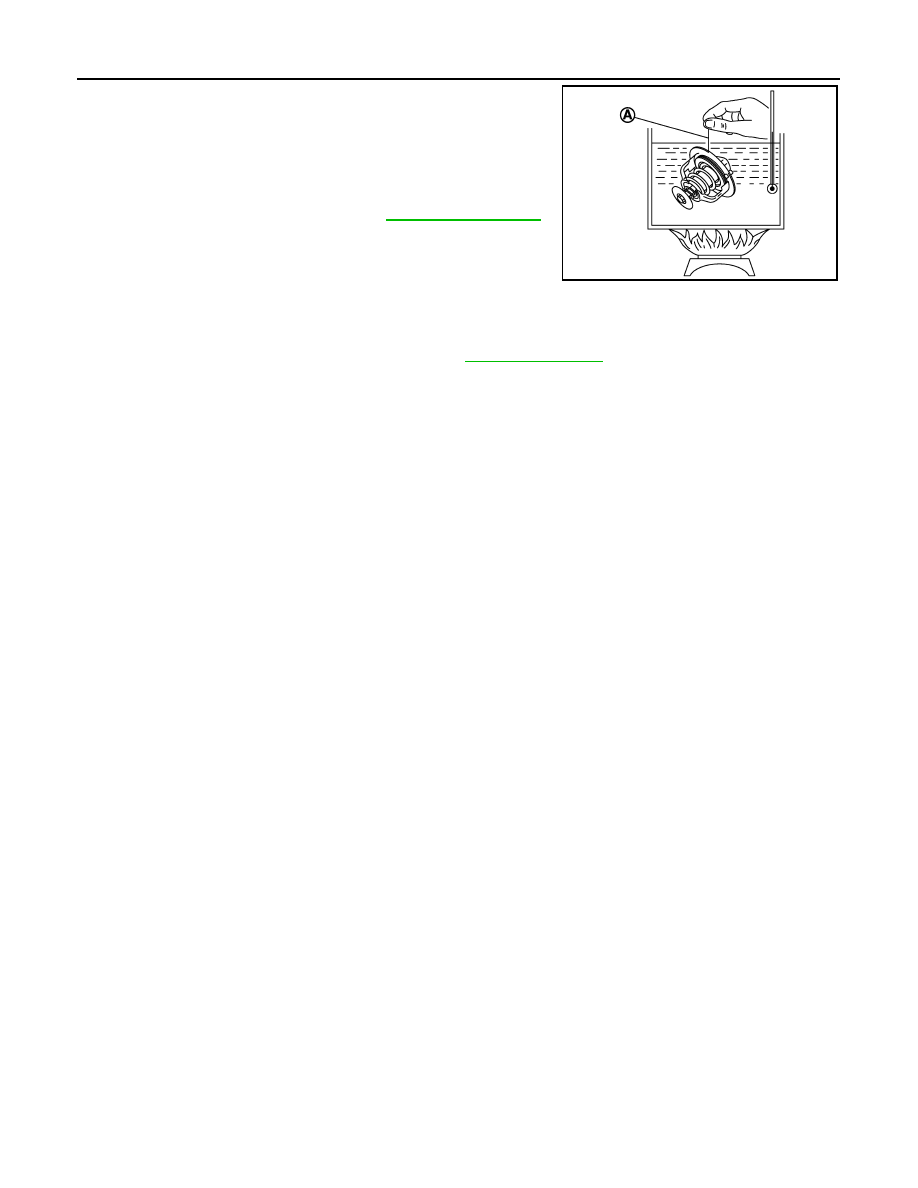
• Place a thread (A) so that it is caught in the valve of the thermostat.
Immerse fully in a container filled with water. Heat while stirring.
• The valve opening temperature is the temperature at which the
valve opens and falls from the thread.
• After checking the maximum valve lift, lower the water temperature
and check the valve closing temperature.
• If the malfunctioning condition, when valve seating at ordinary
room temperature, or measured values are out of the standard,
replace thermostat.
INSPECTION AFTER INSTALLATION
• Check that the reservoir tank cap is tightened.
• Check for leakage of engine coolant using the radiator cap tester adapter (commercial service tool) and the
radiator cap tester (commercial service tool). Refer to
.
• Start and warm up the engine. Visually check that there is no leakage of engine coolant.
Thermostat (Standard)
: Refer to
.
JPBIA2313ZZ
Нет комментариевНе стесняйтесь поделиться с нами вашим ценным мнением.
Текст