Infiniti FX35, FX50 (S51). Manual — part 951

EM-104
< UNIT DISASSEMBLY AND ASSEMBLY >
[VQ35HR]
OIL PAN (UPPER)
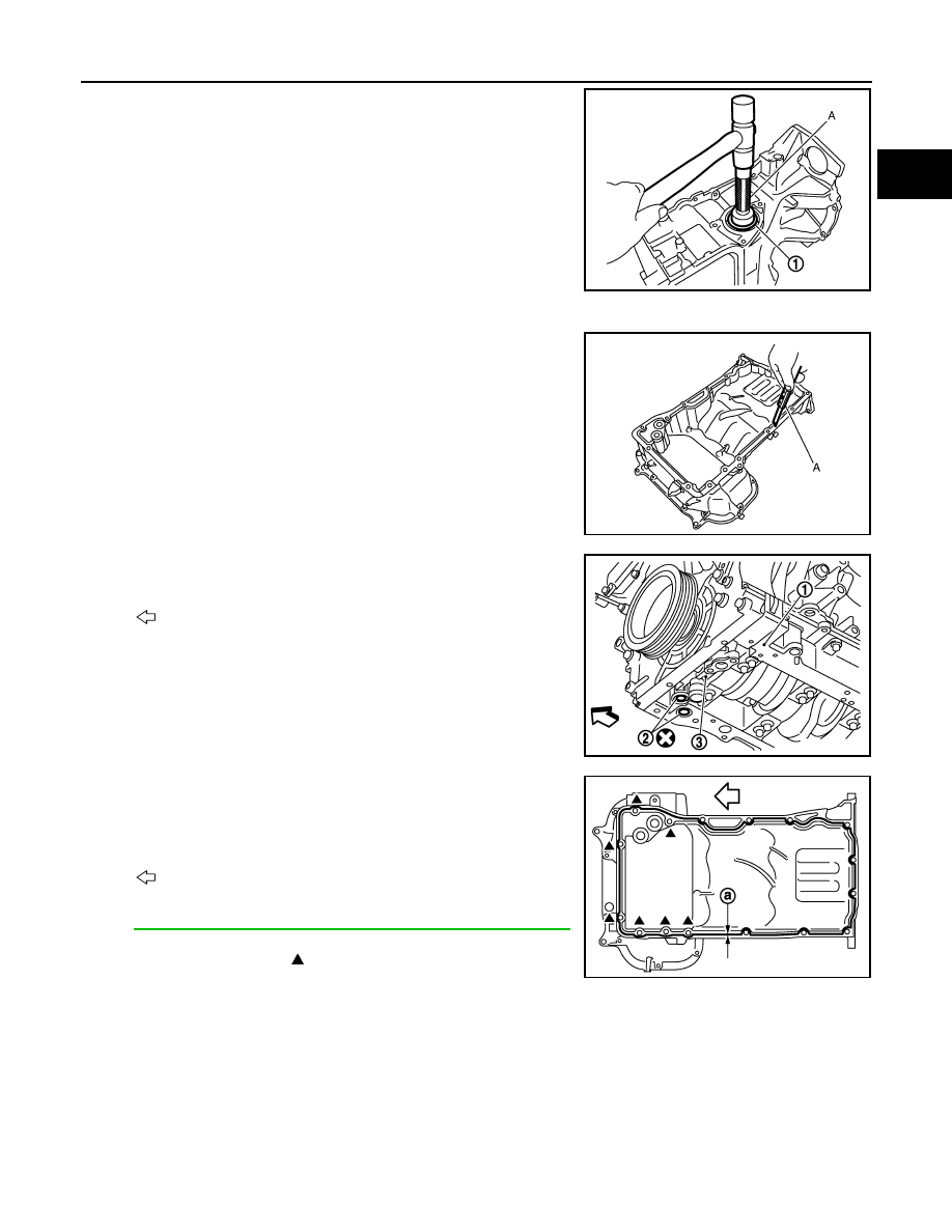
5.
Loosen mounting bolts in the reverse order as shown in the fig-
ure with power tool to remove.
• Insert the seal cutter [SST: KV10111100 (J-37228)] between
oil pan (upper) and lower cylinder block. Slide seal cutter by
tapping on the side of tool with a hammer. Remove oil pan
(upper).
CAUTION:
• Be careful not to damage the mating surfaces.
• Never insert a screwdriver, this will damage the mating
surfaces.
6.
Remove O-rings (2) from bottom of lower cylinder block (1) and
oil pump (3).
7.
Remove axle pipe, if necessary.
• Remove axle pipe from oil pan (upper) using a suitable drift (A)
[outer diameter: 37 mm (1.46 in)].
INSTALLATION
1.
Install axle pipe (3) to oil pan (upper), if removed.
• Lubricate O-ring groove of axle pipe, O-rings (1), (2), and O-
ring joint of oil pan with new engine oil.
Unit: mm (in)
: Engine front
JPBIA0022ZZ
: Engine front
JPBIA1330ZZ
JPBIA0028ZZ
Items
O-ring inner diameter
Final drive side (right side)
31.4 (1.236)
Axle pipe flange side (left side)
33.6 (1.323)
JPBIA0452ZZ
OIL PAN (UPPER)
EM-105
< UNIT DISASSEMBLY AND ASSEMBLY >
[VQ35HR]
C
D
E
F
G
H
I
J
K
L
M
A
EM
N
P
O
• Install axle pipe (1) to oil pan (upper) from axle pipe flange
side (left side) using a suitable drift (A) [outer diameter: 43 to
57 mm (1.69 to 2.24 in)].
CAUTION:
Insert it with care to prevent O-ring from sliding.
2.
Install oil pan (upper) as per the following:
a.
Use a scraper (A) to remove old liquid gasket from mating sur-
faces.
CAUTION:
Never scratch or damage the mating surfaces when clean-
ing off old liquid gasket.
• Also remove old liquid gasket from mating surface of lower cyl-
inder block.
• Remove old liquid gasket from the bolt holes and threads.
b.
Install new O-rings (2) on the bottom of lower cylinder block (1)
and oil pump (3).
c.
Apply a continuous bead of liquid gasket with the tube presser
(commercial service tool) to the cylinder block mating surface of
oil pan (upper) to a limited portion as shown in the figure.
Use Genuine RTV Silicone Sealant or an equivalent. Refer
to
GI-16, "Recommended Chemical Products and Sealants"
CAUTION:
• For bolt holes with marks (7 locations), apply liquid
gasket outside the holes.
• Attaching must be done within 5 minutes after coating.
d.
Install oil pan (upper).
CAUTION:
Install avoiding misalignment of O-rings.
JPBIA0029ZZ
JPBIA0027ZZ
: Engine front
JPBIA1330ZZ
a
:
φ
4.0 - 5.0 mm (0.157 - 0.197 in)
: Engine front
JPBIA0388ZZ
EM-106
< UNIT DISASSEMBLY AND ASSEMBLY >
[VQ35HR]
OIL PAN (UPPER)
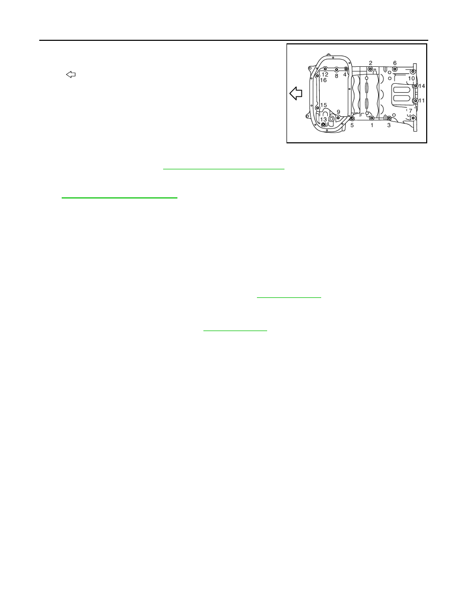
• Tighten mounting bolts in numerical order as shown in the fig-
ure.
• There are three types of mounting bolts. Refer to the following
for locating bolts.
3.
Install oil strainer to oil pump.
4.
Install oil pan (lower). Refer to
EM-47, "Removal and Installation"
.
5.
Install oil pan drain plug.
• Refer to the figure of components of former page for installation direction of drain plug washer. Refer to
.
6.
Install in the reverse order of removal after this step.
NOTE:
At least 30 minutes after oil pan is installed, pour engine oil.
AWD : Inspection
INFOID:0000000005245172
INSPECTION AFTER REMOVAL
Clean oil strainer if any object attached.
INSPECTION AFTER INSTALLATION
1.
Check the engine oil level and adjust engine oil. Refer to
2.
Start engine, and check there is no leakage of engine oil.
3.
Stop engine and wait for 10 minutes.
4.
Check the engine oil level again. Refer to
.
: Engine front
M8
×
25 mm (0.98 in)
: 3, 6, 8, 9, 11, 12, 14, 15, 16
M8
×
50 mm (1.97 in)
: 2
M8
×
90 mm (3.54 in)
: 1, 4, 5, 7, 10, 13
JPBIA0022ZZ
CYLINDER HEAD
EM-107
< UNIT DISASSEMBLY AND ASSEMBLY >
[VQ35HR]
C
D
E
F
G
H
I
J
K
L
M
A
EM
N
P
O
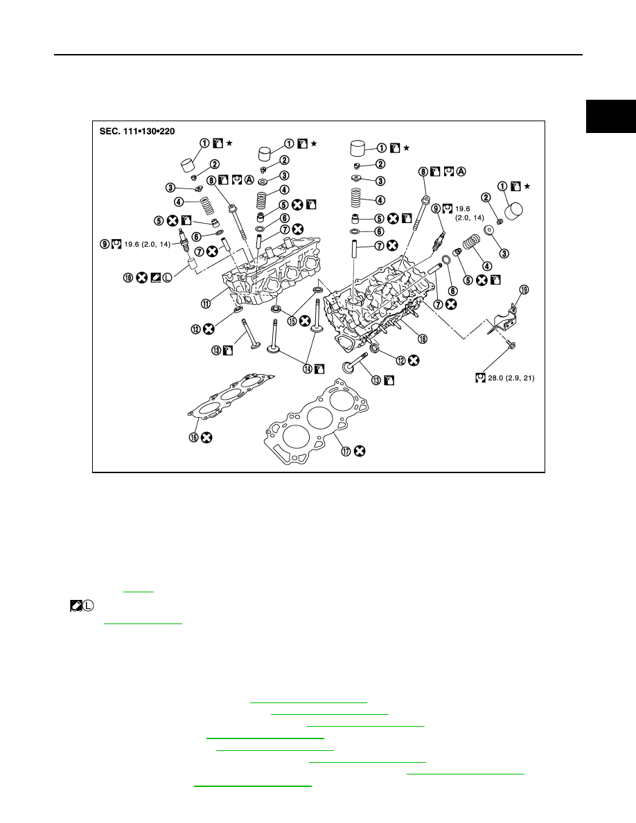
CYLINDER HEAD
Exploded View
INFOID:0000000005245173
Disassembly and Assembly
INFOID:0000000005245174
DISASSEMBLY
1.
Remove the following parts:
• Intake manifold collector: Refer to
.
• Rocker cover and spark plug: Refer to
• Fuel tube and fuel injector assembly: Refer to
• Intake manifold: Refer to
• Exhaust manifold: Refer to
• Water inlet and thermostat assembly: Refer to
.
• Water outlets (front and rear), water pipe and heater pipe: Refer to
• Timing chain: Refer to
1.
Valve lifter
2.
Valve collet
3.
Valve spring retainer
4.
Valve spring
5.
Valve oil seal
6.
Valve spring seat
7.
Valve guide
8.
Cylinder head bolt
9.
Spark plug
10. Spark plug tube
11.
Cylinder head (bank 1)
12. Valve seat (EXH)
13. Valve (EXH)
14. Valve (INT)
15. Valve seat (INT)
16. Cylinder head gasket (bank 1)
17. Cylinder head gasket (bank 2)
18. Cylinder head (bank 2)
19. Engine rear lower slinger
A.
Refer to
: Apply high strength thread locking sealant or equivalent.
Refer to
for symbols not described on the above.
JPBIA1826GB
Нет комментариевНе стесняйтесь поделиться с нами вашим ценным мнением.
Текст