Infiniti FX35, FX50 (S51). Manual — part 952
EM-108
< UNIT DISASSEMBLY AND ASSEMBLY >
[VQ35HR]
CYLINDER HEAD
• Rear timing chain case: Refer to
.
• Camshaft: Refer to
.
2.
Remove cylinder head.
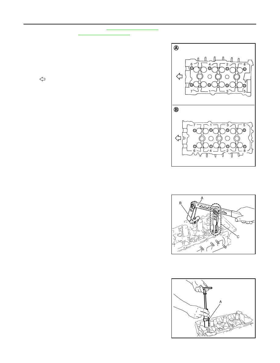
• Loosen cylinder head bolts in reverse order as shown in the
figure with cylinder head bolt wrench (commercial service tool)
and power tool.
3.
Remove cylinder head gaskets.
4.
Remove valve lifter.
• Identify installation positions, and store them without mixing them up.
5.
Remove valve collet.
• Compress valve spring with the valve spring compressor [SST:
KV10116200 (J-26336-A)] (A), the attachment [SST:
KV10115900 (J-26336-20)] (C) and the adapter [SST:
KV10109220 (
—
)] (B). Remove valve collet with a magnet
hand.
CAUTION:
When working, take care not to damage valve lifter holes.
6.
Remove valve spring retainer, valve spring and valve spring seat.
7.
Push valve stem to combustion chamber side, and remove valve.
• Identify installation positions, and store them without mixing them up.
8.
Remove valve oil seal using the valve oil seal puller [SST:
KV10107902 (J-38959)] (A).
9.
Remove valve seat, if valve seat must be replaced.
A
: Bank 1
B
: Bank 2
: Engine front
JPBIA0172ZZ
JPBIA0180ZZ
JPBIA0177ZZ
CYLINDER HEAD
EM-109
< UNIT DISASSEMBLY AND ASSEMBLY >
[VQ35HR]
C
D
E
F
G
H
I
J
K
L
M
A
EM
N
P
O
• Bore out old seat until it collapses. Boring should not continue beyond the bottom face of the seat
recess in cylinder head. Set the machine depth stop to ensure this. Refer to
CAUTION:
Prevent to scratch cylinder head by excessive boring.
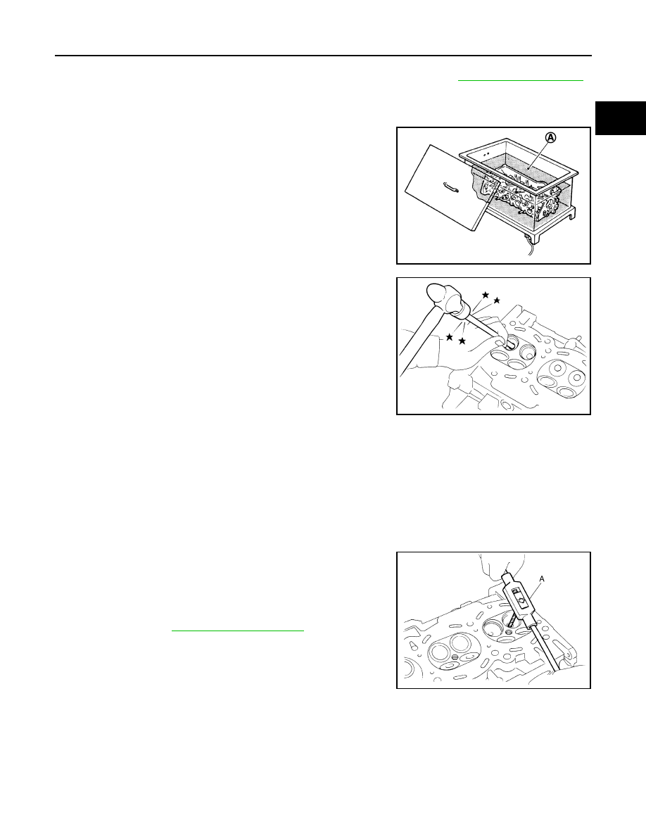
10. Remove valve guide, if valve guide must be replaced.
a.
To remove valve guide, heat cylinder head to 110 to 130
°
C (230
to 266
°
F) by soaking in heated oil (A).
b.
Drive out valve guide with a press [under a 20 kN (2 ton, 2.2 US
ton, 2.0 lmp ton) pressure] or a hammer and the valve guide drift
(commercial service tool).
WARNING:
Cylinder head contains heat. When working, wear protec-
tive equipment to avoid getting burned.
11. Remove spark plug tube, if necessary.
• Using a pliers, pull spark plug tube out of cylinder head.
CAUTION:
• Take care not to damage cylinder head.
• Once removed, spark plug tube will be deformed and cannot be reused. Never remove it unless
absolutely necessary.
ASSEMBLY
1.
If valve guide is removed in step 10 (DISASSEMBLY), install it.
Replace with oversized [0.2 mm (0.008 in)] valve guide.
a.
Using the valve guide reamer (commercial service tool) (A),
ream cylinder head valve guide hole.
JPBIA0184ZZ
SEM931C
Valve guide hole diameter (for service parts):
Intake and exhaust
: Refer to
JPBIA0185ZZ
EM-110
< UNIT DISASSEMBLY AND ASSEMBLY >
[VQ35HR]
CYLINDER HEAD
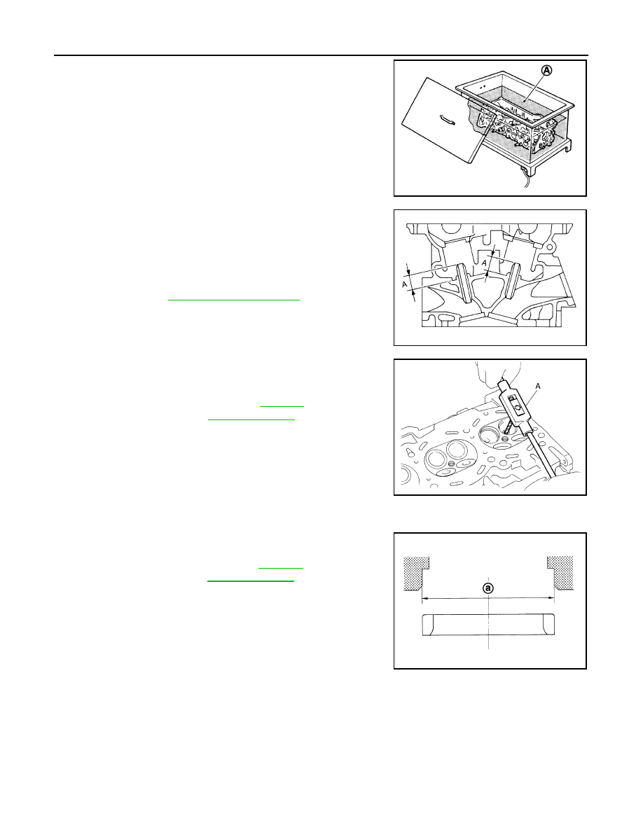
b.
Heat cylinder head to 110 to 130
°
C (230 to 266
°
F) by soaking in
heated oil (A).
c.
Using the valve guide drift (commercial service tool), press valve
guide from camshaft side to the dimensions as shown in the fig-
ure.
WARNING:
Cylinder head contains heat. When working, wear protec-
tive equipment to avoid getting burned.
d.
Using the valve guide reamer (commercial service tool) (A),
apply reamer finish to valve guide.
2.
If valve seat is removed in step 9 (DISASSEMBLY), install it.
Replace with oversize [0.5 mm (0.020 in)] valve seat.
a.
Ream cylinder head recess diameter (a) for service valve seat.
• Be sure to ream in circles concentric to valve guide center.
This enables valve to fit correctly.
JPBIA0184ZZ
Projection (A)
Intake and exhaust
: Refer to
JPBIA0186ZZ
Standard
: Refer to
.
(Intake and exhaust)
JPBIA0185ZZ
Oversize
: Refer to
.
(Intake and exhaust)
JPBIA0188ZZ
CYLINDER HEAD
EM-111
< UNIT DISASSEMBLY AND ASSEMBLY >
[VQ35HR]
C
D
E
F
G
H
I
J
K
L
M
A
EM
N
P
O
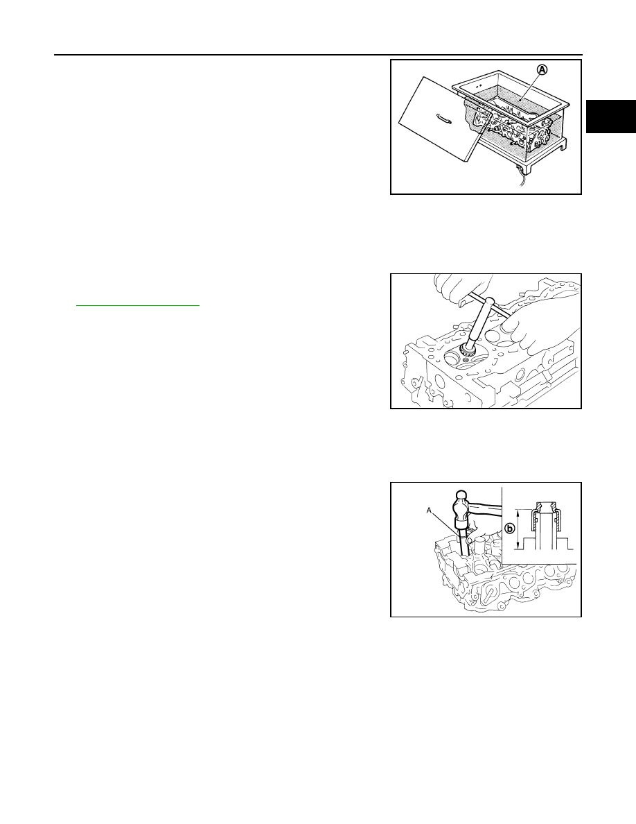
b.
Heat cylinder head to 110 to 130
°
C (230 to 266
°
F) by soaking in
heated oil (A).
c.
Provide valve seats cooled well with dry ice. Force fit valve seat into cylinder head.
WARNING:
Cylinder head contains heat. When working, wear protective equipment to avoid getting burned.
CAUTION:
Never directly touching cold valve seats.
d.
Using the valve seat cutter set (commercial service tool) or valve
seat grinder, finish seat to the specified dimensions. Refer to
CAUTION:
When using the valve seat cutter, firmly grip cutter handle
with both hands. Then, press on the contacting surface all
around the circumference to cut in a single drive. Improper
pressure on with cutter or cutting many different times may
result in stage valve seat.
e.
Using compound, grind to adjust valve fitting.
f.
Check again for normal contact.
3.
Install new valve oil seals as per the following:
a.
Apply new engine oil on valve oil seal joint and seal lip.
b.
Install with the valve oil seal drift [SST: KV10115600 (J-38958)]
(A) to match dimension in the figure.
4.
Install valve spring seat.
5.
Install valve.
NOTE:
Larger diameter valves are for intake side.
6.
Install valve spring (uneven pitch type).
JPBIA0184ZZ
SEM934C
Height (b) (Without valve spring seat installed)
Intake and exhaust
: 14.3 - 14.9 mm (0.563 - 0.587 in)
JPBIA0178ZZ
Нет комментариевНе стесняйтесь поделиться с нами вашим ценным мнением.
Текст