Infiniti FX35, FX50 (S51). Manual — part 950
EM-100
< UNIT DISASSEMBLY AND ASSEMBLY >
[VQ35HR]
OIL PAN (UPPER)
OIL PAN (UPPER)
2WD
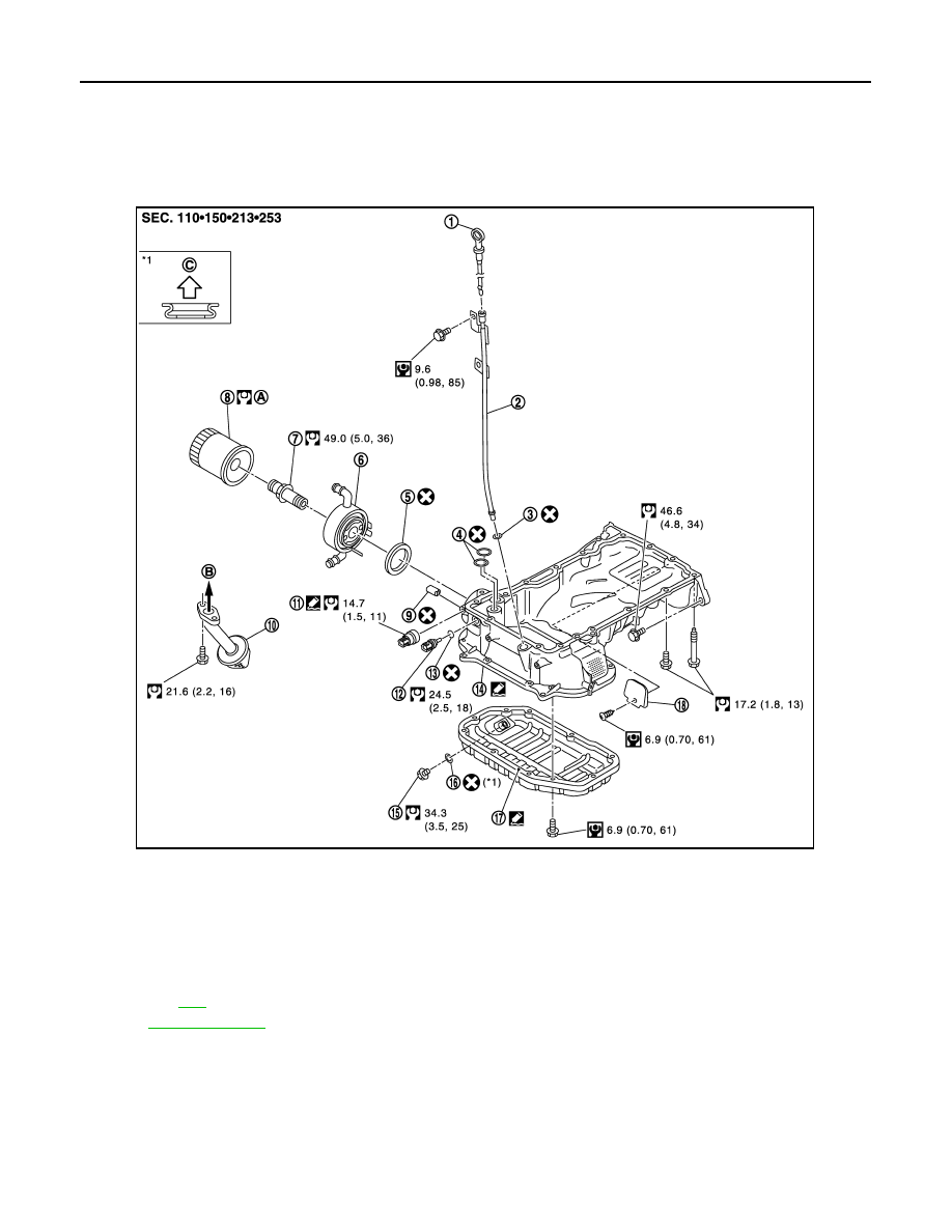
2WD : Exploded View
INFOID:0000000005245167
2WD : Disassembly and Assembly
INFOID:0000000005245168
REMOVAL
CAUTION:
Never drain engine oil when the engine is hot to avoid the danger of being scalded.
1.
Remove oil level gauge, oil pressure switch and oil temperature sensor.
1.
Oil level gauge
2.
Oil level gauge guide
3.
O-ring
4.
O-ring
5.
O-ring
6.
Oil cooler
7.
Connector bolt
8.
Oil filter
9.
Relief valve
10. Oil strainer
11.
Oil pressure switch
12. Oil temperature sensor
13. Washer
14. Oil pan (upper)
15. Drain plug
16. Drain plug washer
17. Oil pan (lower)
18. Rear plate cover
A.
Refer to
B.
To oil pump
C.
Oil pan side
for symbols in the figure.
JPBIA1940GB
OIL PAN (UPPER)
EM-101
< UNIT DISASSEMBLY AND ASSEMBLY >
[VQ35HR]
C
D
E
F
G
H
I
J
K
L
M
A
EM
N
P
O
2.
Remove oil pan (lower). Refer to
EM-47, "Removal and Installation"
3.
Remove oil strainer.
4.
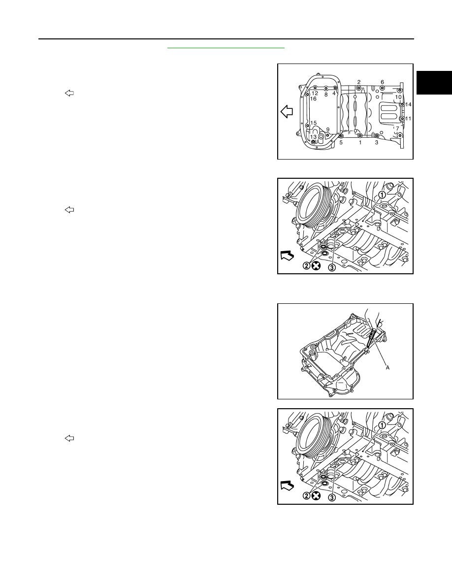
Loosen mounting bolts in the reverse order as shown in the fig-
ure with power tool to remove.
• Insert the seal cutter [SST: KV10111100 (J-37228)] between
oil pan (upper) and lower cylinder block. Slide seal cutter by
tapping on the side of tool with a hammer. Remove oil pan
(upper).
CAUTION:
• Be careful not to damage the mating surfaces.
• Never insert a screwdriver, this will damage the mating
surfaces.
5.
Remove O-rings (2) from bottom of lower cylinder block (1) and
oil pump (3).
INSTALLATION
1.
Install oil pan (upper) as per the following:
a.
Use a scraper (A) to remove old liquid gasket from mating sur-
faces.
CAUTION:
Never scratch or damage the mating surfaces when clean-
ing off old liquid gasket.
• Also remove old liquid gasket from mating surface of lower cyl-
inder block.
• Remove old liquid gasket from the bolt holes and threads.
b.
Install new O-rings (2) on the bottom of lower cylinder block (1)
and oil pump (3).
: Engine front
JPBIA0022ZZ
: Engine front
JPBIA1330ZZ
JPBIA0027ZZ
: Engine front
JPBIA1330ZZ
EM-102
< UNIT DISASSEMBLY AND ASSEMBLY >
[VQ35HR]
OIL PAN (UPPER)
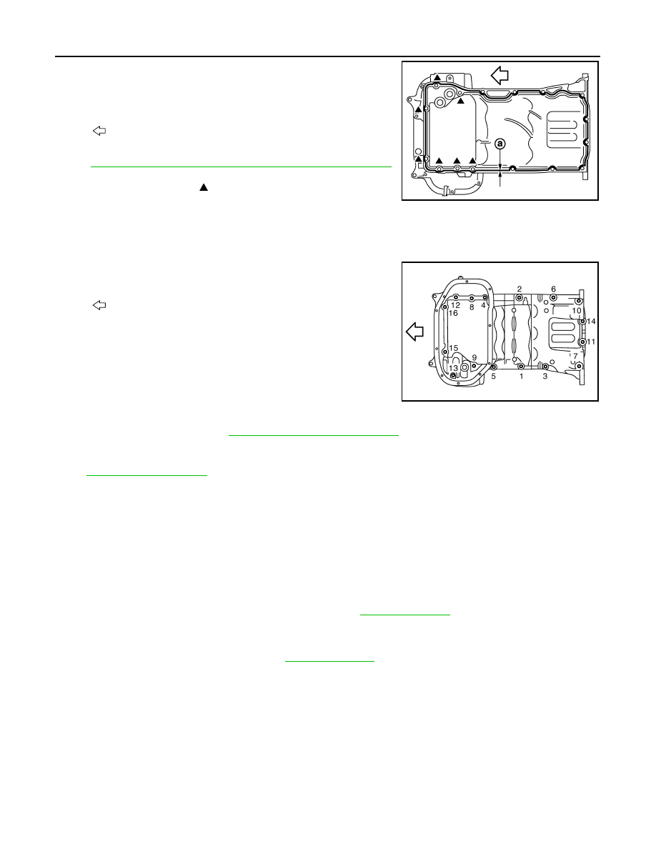
c.
Apply a continuous bead of liquid gasket with the tube presser
(commercial service tool) to the cylinder block mating surface of
oil pan (upper) to a limited portion as shown in the figure.
Use Genuine RTV Silicone Sealant or an equivalent. Refer
to
GI-16, "Recommended Chemical Products and Sealants"
.
CAUTION:
• For bolt holes with marks (7 locations), apply liquid
gasket outside the holes.
• Attaching must be done within 5 minutes after coating.
d.
Install oil pan (upper).
CAUTION:
Install avoiding misalignment of both O-rings.
• Tighten mounting bolts in numerical order as shown in the fig-
ure.
• There are two types of mounting bolts. Refer to the following
for locating bolts.
2.
Install oil strainer to oil pump.
3.
Install oil pan (lower). Refer to
EM-47, "Removal and Installation"
.
4.
Install oil pan drain plug.
• Refer to the figure of components of former page for installation direction of drain plug washer. Refer to
.
5.
Install in the reverse order of removal after this step.
NOTE:
At least 30 minutes after oil pan is installed, pour engine oil.
2WD : Inspection
INFOID:0000000005245169
INSPECTION AFTER REMOVAL
Clean oil strainer if any object attached.
INSPECTION AFTER INSTALLATION
1.
Check the engine oil level and adjust engine oil. Refer to
2.
Start engine, and check there is no leakage of engine oil.
3.
Stop engine and wait for 10 minutes.
4.
Check the engine oil level again. Refer to
.
AWD
a
:
φ
4.0 - 5.0 mm (0.157 - 0.197 in)
: Engine front
: Engine front
M8
×
90 mm (3.54 in)
: 7, 10, 13
M8
×
25 mm (0.98 in)
: Except the above
JPBIA0388ZZ
JPBIA0022ZZ
OIL PAN (UPPER)
EM-103
< UNIT DISASSEMBLY AND ASSEMBLY >
[VQ35HR]
C
D
E
F
G
H
I
J
K
L
M
A
EM
N
P
O
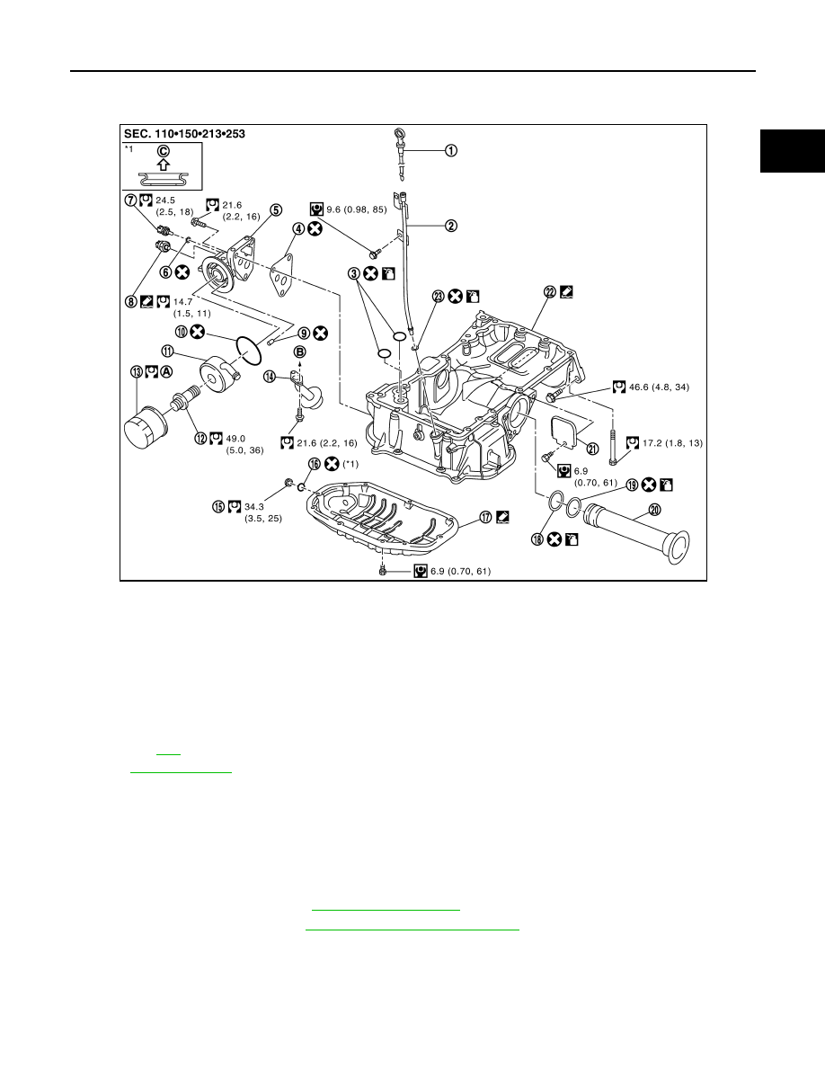
AWD : Exploded View
INFOID:0000000005245170
AWD : Disassembly and Assembly
INFOID:0000000005245171
REMOVAL
CAUTION:
Never drain engine oil when the engine is hot to avoid the danger of being scalded.
1.
Remove oil level gauge, oil pressure switch and oil temperature sensor.
2.
Remove oil filter bracket. Refer to
.
3.
Remove oil pan (lower). Refer to
EM-47, "Removal and Installation"
4.
Remove oil strainer.
1.
Oil level gauge
2.
Oil level gauge guide
3.
O-ring
4.
Gasket
5.
Oil filter bracket
6.
Washer
7.
Oil temperature sensor
8.
Oil pressure sensor
9.
Relief valve
10. O-ring
11.
Oil cooler
12. Connector bolt
13. Oil filter
14. Oil strainer
15. Drain plug
16. Oil pan drain plug
17. Oil pan (lower)
18. O-ring (small)
19. O-ring (large)
20. Axle pipe
21. Rear plate cover
22. Oil pan (upper)
23. O-ring
A.
Refer to
B.
To oil pump
C.
Oil pan side
Refer to
for symbols in the figure.
JPBIA1847GB
Нет комментариевНе стесняйтесь поделиться с нами вашим ценным мнением.
Текст