Infiniti FX35, FX50 (S51). Manual — part 1846

DIAGNOSIS AND REPAIR WORK FLOW
TM-191
< BASIC INSPECTION >
[7AT: RE7R01B (VK50VE)]
C
E
F
G
H
I
J
K
L
M
A
B
TM
N
O
P
Symptoms
Vehicle does not move (
Any position
Particular position )
No up-shift (
1GR
→
2GR
2GR
→
3GR
3GR
→
4GR
4GR
→
5GR
5GR
→
6GR
6GR
→
7GR)
No down-shift (
7GR
→
6GR
6GR
→
5GR
5GR
→
4GR
4GR
→
3GR
3GR
→
2GR
2GR
→
1GR)
Lock-up malfunction
Shift point too high or too low
Shift shock or slip
Noise or vibration
No kick down
No pattern select
Others
Frequency
All the time
Under certain conditions
Sometimes ( times a day)
Weather conditions
Not affected
Weather
Fine
Clouding
Raining
Snowing
Other ( )
Temp.
Hot
Warm
Cool
Cold
Temp. [Approx.
°
C (
°
F)]
Humidity
High
Middle
Low
Transmission conditions
Not affected
Cold
During warm-up
After warm-up
Engine speed ( rpm)
Road conditions
Not affected
In town
In suburbs
Freeway
Off road (Up / Down)
Driving conditions
Not affected
At starting
While idling
While engine racing
At racing
While cruis-
ing
While accelerating
While decelerating
While turning (Right / Left)
Vehicle speed [ km/h ( MPH)]
Other conditions
Question Sheet
TM-192
< SYSTEM DESCRIPTION >
[7AT: RE7R01B (VK50VE)]
A/T CONTROL SYSTEM
SYSTEM DESCRIPTION
A/T CONTROL SYSTEM
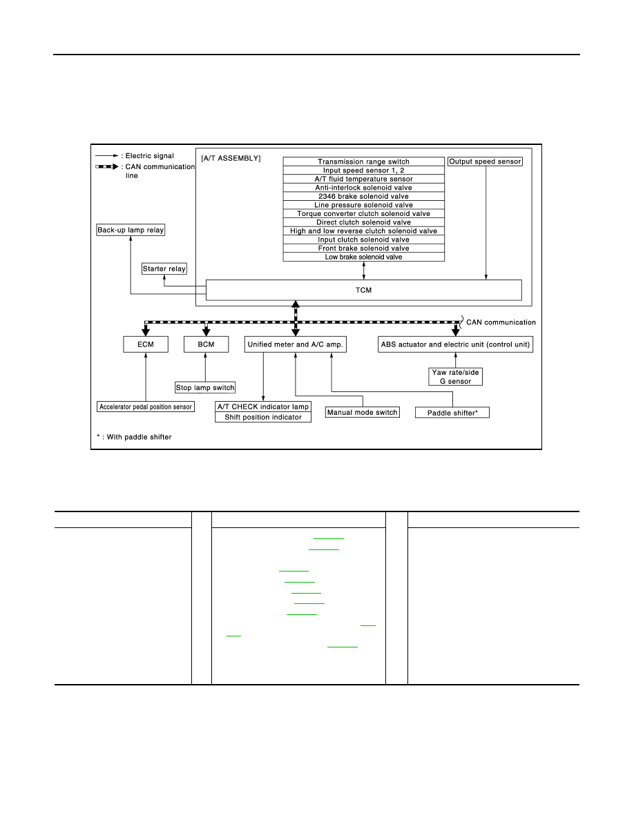
System Diagram
INFOID:0000000005250187
System Description
INFOID:0000000005250188
INPUT/OUTPUT SIGNAL CHART
SYSTEM DESCRIPTION
• The A/T senses vehicle operating conditions through various sensors or signals. It always controls the opti-
mum shift position and reduces shifting and lock-up shocks.
• Receive input signals transmitted from various switches and sensors.
• Determine required line pressure, shifting point, lock-up operation, etc.
• Transmit required output signals to the respective solenoids.
JSDIA1473GB
Switch, Sensor or Signal
⇒
TCM function
⇒
Actuator
• Transmission range switch
• Accelerator pedal position sig-
nal
• Closed throttle position signal
• Wide open throttle position sig-
nal
• Engine speed signal
• A/T fluid temperature sensor
• Output speed sensor
• Vehicle speed signal
• Manual mode switch signal
• Stop lamp switch signal
• Side G sensor signal
• Input speed sensor 1, 2
• Line pressure control (
• Shift change control (
)
• Shift pattern control
- Shift pattern (
)
- Manual mode (
)
• Lock-up control (
)
• Fail-safe control (
• Self-diagnosis (
)
• CONSULT-III communication line (
• CAN communication line (
)
• Input clutch solenoid valve
• Direct clutch solenoid valve
• Front brake solenoid valve
• High and low reverse clutch solenoid
valve
• Low brake solenoid valve
• Torque converter clutch solenoid valve
• Line pressure solenoid valve
• Anti-interlock solenoid valve
• 2346 brake solenoid valve
• A/T CHECK indicator lamp
• Back-up lamp relay
• Starter relay
A/T CONTROL SYSTEM
TM-193
< SYSTEM DESCRIPTION >
[7AT: RE7R01B (VK50VE)]
C
E
F
G
H
I
J
K
L
M
A
B
TM
N
O
P
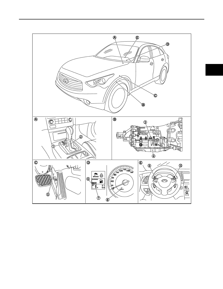
Component Parts Location
INFOID:0000000005250189
NOTE:
• The following components are included in A/T shift selector assembly.
- Manual mode select switch
- Manual mode position select switch
- Shift position switch
• The following components are included in control valve with TCM.
- TCM
- Input speed sensor 1, 2
1.
Selector lever position indicator
2.
A/T shift selector assembly
3.
A/T assembly connector
4.
Control valve with TCM
*1
5.
Accelerator pedal position sensor
6.
Manual mode indicator
7.
Shift position indicator
8.
A/T CHECK indicator lamp
9.
Paddle shifter (shift-down)
*2
10. Paddle shifter (shift-up)
*2
A.
Center console
B.
A/T assembly
C.
Accelerator pedal
D.
Combination meter
E.
Steering wheel
JSDIA0787ZZ

TM-194
< SYSTEM DESCRIPTION >
[7AT: RE7R01B (VK50VE)]
A/T CONTROL SYSTEM
- Output speed sensor
- A/T fluid temperature sensor
- Transmission range switch
- Direct clutch solenoid valve
- High and low reverse clutch solenoid valve
- Input clutch solenoid valve
- Front brake solenoid valve
- Low brake solenoid valve
- Anti-interlock solenoid valve
- 2346 brake solenoid valve
- Line pressure solenoid valve
- Torque converter clutch solenoid valve
*1: Control valve with TCM is included in A/T assembly.
*2: With paddle shifter
Component Description
INFOID:0000000005250190
*: With paddle shifter
Name
Function
TCM
The TCM consists of a microcomputer and connectors for signal input and output and
for power supply. The TCM controls the A/T.
Transmission range switch
Output speed sensor
Input speed sensor 1
Input speed sensor 2
A/T fluid temperature sensor
Input clutch solenoid valve
Front brake solenoid valve
Direct clutch solenoid valve
High and low reverse clutch solenoid valve
Low brake solenoid valve
Anti-interlock solenoid valve
2346 brake solenoid valve
Line pressure solenoid valve
Torque converter clutch solenoid valve
Accelerator pedal position sensor
Manual mode switch
Paddle shifter*
Starter relay
A/T CHECK indicator lamp
When the ignition switch is pushed to the ON position, the light comes on for 2 seconds.
Stop lamp switch
ECM
BCM
Unified meter and A/C amp.
MWI-6, "METER SYSTEM : System Description"
ABS actuator and electric unit (control unit)
Yaw rate/side G sensor
Нет комментариевНе стесняйтесь поделиться с нами вашим ценным мнением.
Текст