Infiniti FX35, FX50 (S51). Manual — part 1845

SERVICE DATA AND SPECIFICATIONS (SDS)
TM-187
< SERVICE DATA AND SPECIFICATIONS (SDS)
[7AT: RE7R01A (VQ35HR)]
C
E
F
G
H
I
J
K
L
M
A
B
TM
N
O
P
SERVICE DATA AND SPECIFICATIONS (SDS)
SERVICE DATA AND SPECIFICATIONS (SDS)
General Specification
INFOID:0000000005250178
*1: Refer to
MA-12, "Fluids and Lubricants"
.
*2: The fluid capacity is the reference value.
Vehicle Speed at Which Gear Shifting Occurs
INFOID:0000000005250179
2WD MODELS
Unit: km/h (MPH)
• At half throttle, the accelerator opening is 4/8 of the full opening.
AWD MODELS
Applied model
2WD
AWD
Transmission model code number
3RX1C
3RX1D
Stall torque ratio
1.92 : 1
Transmission gear ratio
1st
4.924
2nd
3.194
3rd
2.043
4th
1.412
5th
1.000
6th
0.862
7th
0.772
Reverse
3.972
Recommended fluid
Genuine NISSAN Matic S ATF
*1
Fluid capacity
9.2 liter (9-3/4 US qt, 8-1/8 Imp qt)
*2
CAUTION:
• Use only Genuine NISSAN Matic S ATF. Never mix with other ATF.
• Using ATF other than Genuine NISSAN Matic S ATF will cause deterioration driveability and A/T durability, and may damage
the A/T, which is not covered by the INFINITI new vehicle limited warranty.
Gear position
Throttle position
Full throttle
Half throttle
D
1
→
D
2
58 – 62 (36 – 38)
24 – 28 (15 – 17)
D
2
→
D
3
91 – 99 (57 – 61)
50 – 58 (31 – 36)
D
3
→
D
4
143 – 153 (89 – 95)
81 – 91 (51 – 56)
D
4
→
D
5
209 – 219 (130 – 136)
116 – 126 (73 – 78)
D
5
→
D
6
250 – 260 (156 – 161)
174 – 184 (109 – 114)
D
6
→
D
7
250 – 260 (156 – 161)
250 – 260 (156 – 161)
D
7
→
D
6
240 – 250 (150 – 155)
201 – 211 (125 – 131)
D
6
→
D
5
215 – 225 (134 – 139)
127 – 137 (79 – 85)
D
5
→
D
4
197 – 207 (123 – 128)
75 – 85 (47 – 52)
D
4
→
D
3
121 – 131 (76 – 81)
46 – 56 (29 – 34)
D
3
→
D
2
70 – 78 (44 – 48)
22 – 30 (14 – 18)
D
2
→
D
1
23 – 27 (15 – 16)
8 – 12 (5 – 7)

TM-188
< SERVICE DATA AND SPECIFICATIONS (SDS)
[7AT: RE7R01A (VQ35HR)]
SERVICE DATA AND SPECIFICATIONS (SDS)
Unit: km/h (MPH)
• At half throttle, the accelerator opening is 4/8 of the full opening.
Vehicle Speed at Which Lock-up Occurs/Releases
INFOID:0000000005250180
2WD MODELS
• At closed throttle, the accelerator opening is less than 1/8 condition. (Closed throttle position signal OFF)
• At half throttle, the accelerator opening is 4/8 of the full opening.
AWD MODELS
• At closed throttle, the accelerator opening is less than 1/8 condition. (Closed throttle position signal OFF)
• At half throttle, the accelerator opening is 4/8 of the full opening.
Stall Speed
INFOID:0000000005250181
Torque Converter
INFOID:0000000005250184
Gear position
Throttle position
Full throttle
Half throttle
D
1
→
D
2
52 – 56 (33 – 34)
22 – 26 (14 – 16)
D
2
→
D
3
82 – 90 (51 – 55)
45 – 53 (28 – 32)
D
3
→
D
4
129 – 139 (81 – 86)
73 – 83 (46 – 51)
D
4
→
D
5
189 – 199 (118 – 123)
105 – 115 (66 – 71)
D
5
→
D
6
250 – 260 (156 – 161)
157 – 167 (98 – 103)
D
6
→
D
7
250 – 260 (156 – 161)
237 – 247 (148 – 153)
D
7
→
D
6
240 – 250 (150 – 155)
181 – 191 (113 – 118)
D
6
→
D
5
195 – 205 (122 – 127)
115 – 125 (72 – 77)
D
5
→
D
4
179 – 189 (112 – 117)
68 – 78 (43 – 48)
D
4
→
D
3
119 – 129 (74 – 80)
42 – 52 (27 – 32)
D
3
→
D
2
63 – 71 (40 – 44)
20 – 28 (13 – 17)
D
2
→
D
1
21 – 25 (14 – 15)
7 – 11 (5 – 6)
Throttle position
Vehicle speed
km/h (MPH)
Lock-up ON
Lock-up OFF
Closed throttle
54 – 62 (34 – 38)
51 – 59 (32 – 36)
Half throttle
64 – 72 (40 – 44)
61 – 69 (38 – 42)
Throttle position
Vehicle speed
km/h (MPH)
Lock-up ON
Lock-up OFF
Closed throttle
49 – 57 (31 – 35)
46 – 54 (29 – 33)
Half throttle
58 – 66 (37 – 41)
55 – 63 (35 – 39)
Stall speed
2,475 – 2,775 rpm
Dimension between end of converter housing and torque converter
25.0 mm (0.98 in)

DIAGNOSIS AND REPAIR WORK FLOW
TM-189
< BASIC INSPECTION >
[7AT: RE7R01B (VK50VE)]
C
E
F
G
H
I
J
K
L
M
A
B
TM
N
O
P
BASIC INSPECTION
DIAGNOSIS AND REPAIR WORK FLOW
Diagnosis Flow
INFOID:0000000005250185
1.
OBTAIN INFORMATION ABOUT SYMPTOM
1.
and interview the customer to obtain the malfunction information (con-
ditions and environment when the malfunction occurred) as much as possible when the customer brings
in the vehicle.
2.
Check the following:
-
Service history
-
Harnesses and connectors malfunction. Refer to
GI-36, "Intermittent Incident"
.
>> GO TO 2.
2.
CHECK DTC
1.
Before checking the malfunction, check whether any DTC exists.
2.
If DTC exists, perform the following operations.
-
Record the DTC and freeze frame data. (Print out the data using CONSULT-III and affix to the Work Order
Sheet.)
-
Erase DTCs.
-
Check the relationship between the cause that is clarified with DTC and the malfunction information
described by the customer.
is effective.
3.
Check the information of related service bulletins and others also.
Do malfunction information and DTC exist?
Malfunction information and DTC exists. >>GO TO 3.
Malfunction information exists, but no DTC. >>GO TO 4.
No malfunction information, but DTC exists. >>GO TO 5.
3.
REPRODUCE MALFUNCTION SYMPTOM
Check any malfunction described by a customer, except those with DTC on the vehicle.
Also investigate whether the symptom is a fail-safe or normal operation. Refer to
When a malfunction symptom is reproduced, the question sheet is effective. Refer to
.
Verify the relationship between the symptom and the conditions in which the malfunction described by the cus-
tomer occurs.
>> GO TO 5.
4.
REPRODUCE MALFUNCTION SYMPTOM
Check the malfunction described by the customer on the vehicle.
Also investigate whether the symptom is a fail-safe or normal operation. Refer to
When a malfunction symptom is reproduced, the question sheet is effective. Refer to
.
Verify the relationship between the symptom and the conditions in which the malfunction described by the cus-
tomer occurs.
>> GO TO 6.
5.
PERFORM “DTC CONFIRMATION PROCEDURE”
Perform “DTC CONFIRMATION PROCEDURE” of the appropriate DTC to check if DTC is detected again.
Refer to
TM-332, "DTC Inspection Priority Chart"
when multiple DTCs are detected, and then determine the
order for performing the diagnosis.
NOTE:
If no DTC is detected, refer to the freeze frame data.
Is any DTC detected?
YES
>> GO TO 7.
TM-190
< BASIC INSPECTION >
[7AT: RE7R01B (VK50VE)]
DIAGNOSIS AND REPAIR WORK FLOW
NO
>> Check according to
GI-36, "Intermittent Incident"
.
6.
IDENTIFY MALFUNCTIONING SYSTEM WITH “DIAGNOSIS CHART BY SYMPTOM”
Use
from the symptom inspection result in step 4. Then identify where to start per-
forming the diagnosis based on possible causes and symptoms.
>> GO TO 8.
7.
REPAIR OR REPLACE THE MALFUNCTIONING PARTS
Repair or replace the detected malfunctioning parts.
Reconnect parts or connector after repairing or replacing, and then erase DTC if necessary.
>> GO TO 8.
8.
FINAL CHECK
Perform “DTC CONFIRMATION PROCEDURE” again to make sure that the repair is correctly performed.
Check that malfunctions are not reproduced when obtaining the malfunction information from the customer,
referring to the symptom inspection result in step 3 or 4.
Is DTC or malfunction symptom reproduced?
YES-1 >> DTC is reproduced: GO TO 5.
YES-2 >> Malfunction symptom is reproduced: GO TO 6.
NO
>> Before delivering the vehicle to the customer, make sure that DTC is erased.
Question sheet
INFOID:0000000005250186
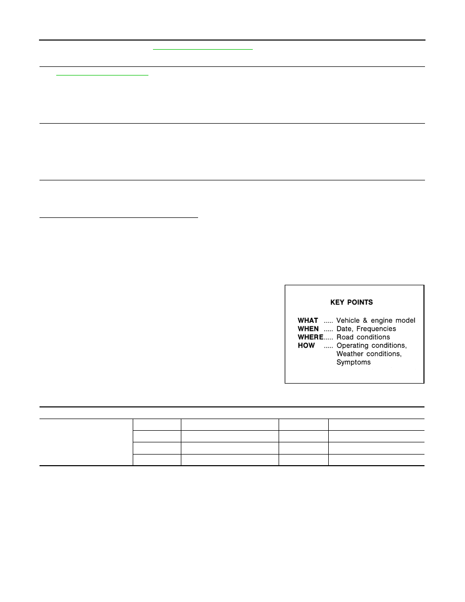
DESCRIPTION
There are many operating conditions that may cause a malfunction
of the transmission parts. By understanding those conditions prop-
erly, a quick and exact diagnosis can be achieved.
In general, customers have their own criteria for a problem. There-
fore, it is important to understand the symptom and status well
enough by asking the customer about the concerns carefully. In
order to systemize all the information for the diagnosis, prepare the
question sheet referring to the question points.
WORKSHEET SAMPLE
SEF907L
Question Sheet
Customer name MR/MS
Engine #
Manuf. Date
Incident Date
VIN
Model & Year
In Service Date
Trans.
Mileage
km/Mile
Нет комментариевНе стесняйтесь поделиться с нами вашим ценным мнением.
Текст