Infiniti FX35, FX50 (S51). Manual — part 1844
TRANSMISSION ASSEMBLY
TM-183
< UNIT REMOVAL AND INSTALLATION >
[7AT: RE7R01A (VQ35HR)]
C
E
F
G
H
I
J
K
L
M
A
B
TM
N
O
P
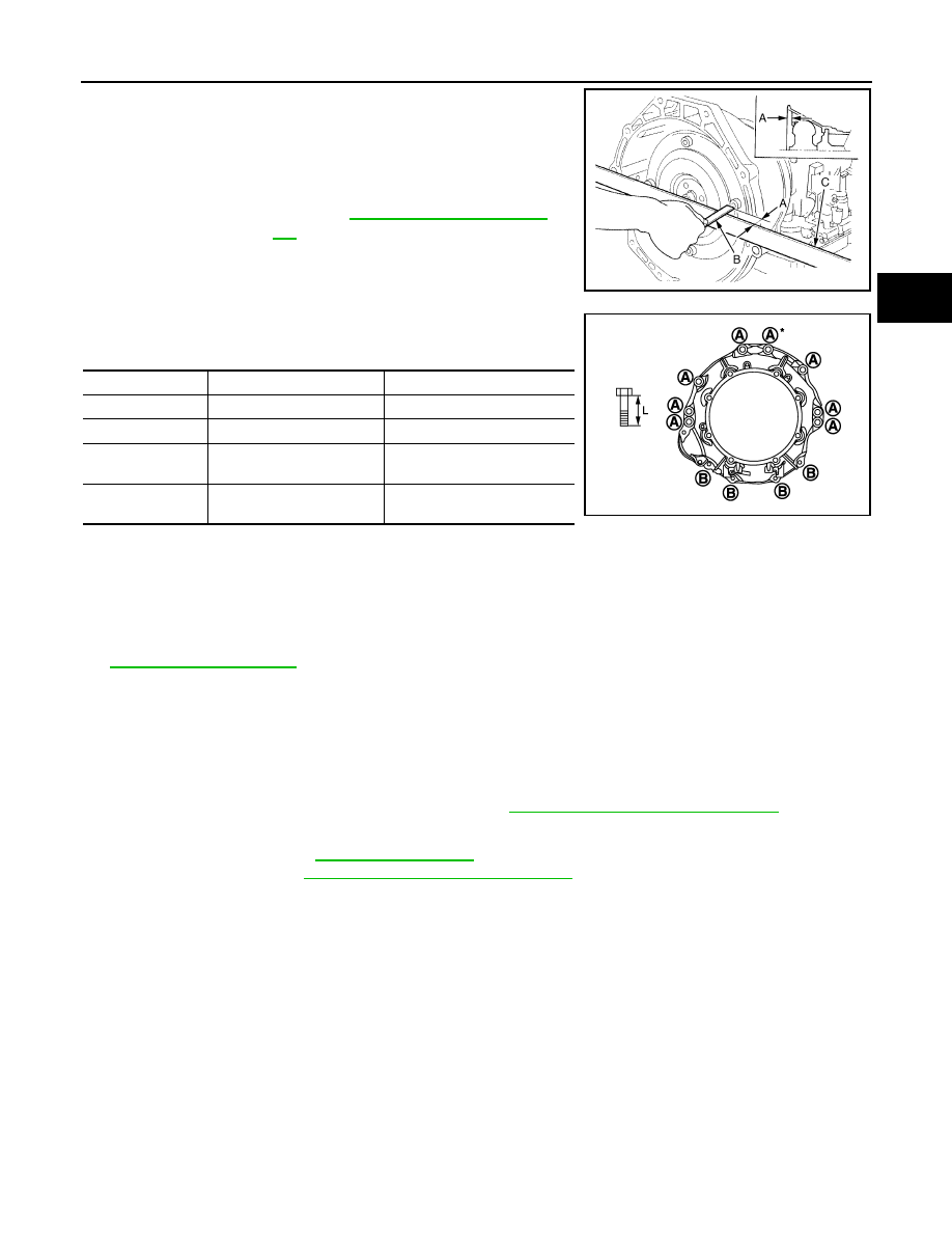
• When installing A/T assembly to the engine, be sure to check
dimension “A” to ensure it is within the reference value limit.
• When installing A/T assembly to the engine, attach the fixing bolts
in accordance with the following standard.
*: Tightening the bolt with bracket.
• Align the positions of tightening bolts for drive plate with those of the torque converter, and temporarily
tighten the bolts. Then, tighten the bolts with the specified torque.
CAUTION:
• When turning crankshaft, turn it clockwise as viewed from the front of the engine.
• When tightening the tightening bolts for the torque converter after fixing the crankshaft pulley
bolts, be sure to confirm the tightening torque of the crankshaft pulley mounting bolts. Refer to
.
• Rotate crankshaft several turns and check to be sure that A/T rotates freely without binding after
converter is installed to drive plate.
2WD : Inspection and Adjustment
INFOID:0000000005250174
INSPECTION AFTER INSTALLATION
• Check A/T fluid leakage.
• Check A/T position after adjusting A/T positions. Refer to
TM-167, "Inspection and Adjustment"
ADJUSTMENT AFTER INSTALLATION
• Adjust A/T fluid level. Refer to
• Adjust A/T position. Refer to
TM-167, "Inspection and Adjustment"
AWD
B
: Scale
C
: Straightedge
Dimension “A”
: Refer to
JPDIA0042ZZ
Bolt symbol
A
B
Insertion direction
A/T assembly to engine
Engine to A/T assembly
Number of bolts
8
4
Bolt length “L”
mm (in)
65 (2.56)
35 (1.38)
Tightening torque
N·m (kg-m, ft-lb)
75 (7.7, 55)
46.6 (4.8, 34)
JPDIA0979ZZ
TM-184
< UNIT REMOVAL AND INSTALLATION >
[7AT: RE7R01A (VQ35HR)]
TRANSMISSION ASSEMBLY
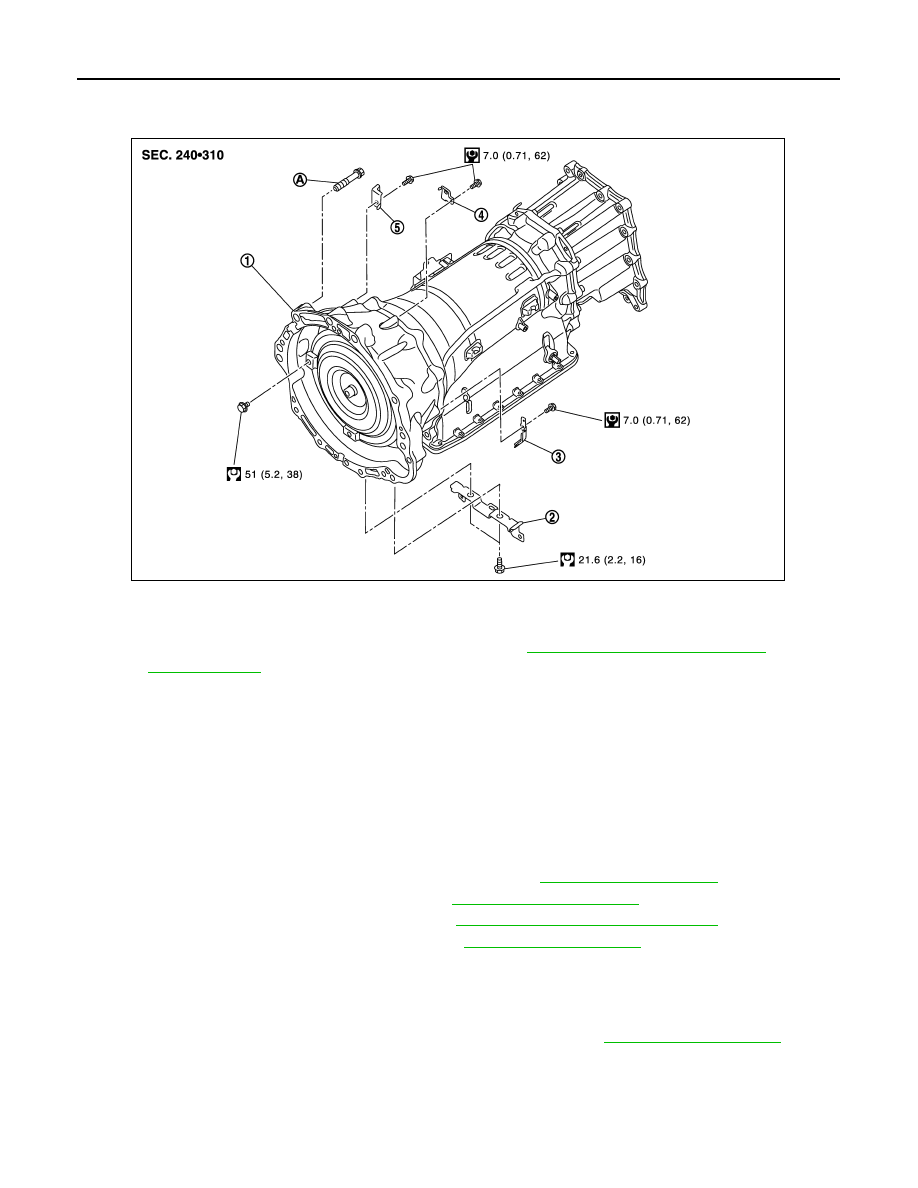
AWD : Exploded View
INFOID:0000000005250175
AWD : Removal and Installation
INFOID:0000000005250176
REMOVAL
CAUTION:
• When removing the A/T assembly from engine, first remove the crankshaft position sensor (POS)
from the A/T assembly.
• Be careful not to damage sensor edge.
1.
Shift the selector lever to “P” position, and then release the parking brake.
2.
Disconnect the battery cable from the negative terminal.
3.
Remove control rod from A/T shift selector assembly. Refer to
4.
Remove propeller shaft assembly (rear). Refer to
5.
Remove propeller shaft assembly (front). Refer to
DLN-109, "VQ35HR : Exploded View"
.
6.
Remove manual lever from A/T assembly. Refer to
.
7.
Support A/T assembly with a transmission jack.
CAUTION:
When setting the transmission jack, be careful not to allow it to collide against the drain plug and
overflow plug.
8.
Remove crankshaft position sensor (POS) from A/T assembly. Refer to
.
CAUTION:
• Never subject it to impact by dropping or hitting it.
• Never disassemble.
• Never allow metal filings, etc. to get on the sensor's front edge magnetic area.
• Never place in an area affected by magnetism.
1.
A/T assembly
2.
Bracket
3.
Bracket
4.
Bracket
5.
Bracket
A.
Tightening must be done following the installation procedure. Refer to
TM-184, "AWD : Removal and Installation"
for symbols in the figure.
JPDIA0849GB
TRANSMISSION ASSEMBLY
TM-185
< UNIT REMOVAL AND INSTALLATION >
[7AT: RE7R01A (VQ35HR)]
C
E
F
G
H
I
J
K
L
M
A
B
TM
N
O
P
9.
Remove starter motor. Refer to
STR-18, "VQ35HR : Exploded View"
.
10. Remove rear plate cover. Refer to
11. Turn crankshaft, and remove the four tightening bolts for drive plate and torque converter.
CAUTION:
When turning the crankshaft, turn it clockwise as viewed from the front of the engine.
12. Remove A/T fluid cooler tubes. Refer to
13. Plug up openings such as the A/T fluid cooler tube hole.
14. Disconnect A/T assembly harness connector and AWD solenoid harness connector.
15. Remove harness and brackets.
16. Remove bolts fixing A/T assembly to engine with a power tool.
17. Remove air breather hose. Refer to
.
18. Remove A/T assembly with transfer assembly from vehicle.
CAUTION:
• Secure torque converter to prevent it from dropping.
• Secure A/T assembly to a transmission jack.
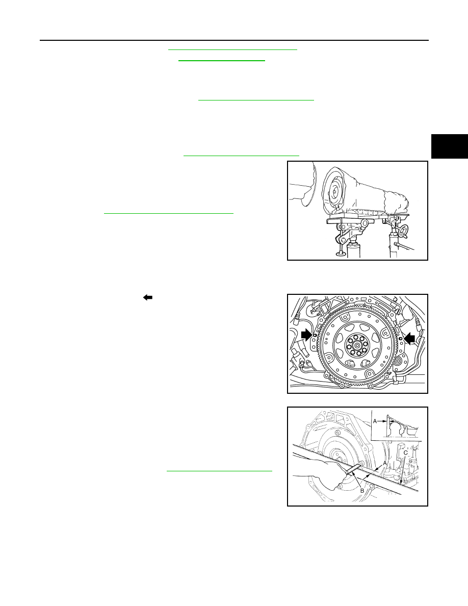
19. Remove transfer assembly from A/T assembly with a power
DLN-65, "VQ35HR : Exploded View"
INSTALLATION
Note the following, and Install in the reverse order of removal.
CAUTION:
Check fitting of dowel pin (
).
• When installing A/T assembly to the engine, be sure to check
dimension “A” to ensure it is within the reference value limit.
SCIA2203E
JPDIA0900ZZ
B
: Scale
C
: Straightedge
Dimension
“A”
: Refer to
.
JPDIA0042ZZ
TM-186
< UNIT REMOVAL AND INSTALLATION >
[7AT: RE7R01A (VQ35HR)]
TRANSMISSION ASSEMBLY
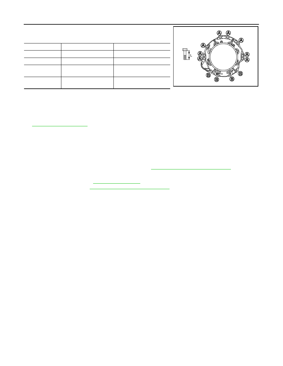
• When installing A/T assembly to the engine, attach the fixing bolts
in accordance with the following standard.
• Align the positions of tightening bolts for drive plate with those of the torque converter, and temporarily
tighten the bolts. Then, tighten the bolts with the specified torque.
CAUTION:
• When turning crankshaft, turn it clockwise as viewed from the front of the engine.
• When tightening the tightening bolts for the torque converter after fixing the crankshaft pulley
bolts, be sure to confirm the tightening torque of the crankshaft pulley mounting bolts. Refer to
.
• Rotate crankshaft several turns and check to be sure that A/T rotates freely without binding after
converter is installed to drive plate.
AWD : Inspection and Adjustment
INFOID:0000000005250177
INSPECTION AFTER INSTALLATION
• Check A/T fluid leakage.
• Check A/T position after adjusting A/T positions. Refer to
TM-167, "Inspection and Adjustment"
ADJUSTMENT AFTER INSTALLATION
• Adjust A/T fluid level. Refer to
• Adjust A/T position. Refer to
TM-167, "Inspection and Adjustment"
Bolt symbol
A
B
Insertion direction
A/T assembly to engine
Engine to A/T assembly
Number of bolts
8
4
Bolt length “L”
mm (in)
65 (2.56)
35 (1.38)
Tightening torque
N·m (kg-m, ft-lb)
75 (7.7, 55)
46.6 (4.8, 34)
JPDIA0851ZZ
Нет комментариевНе стесняйтесь поделиться с нами вашим ценным мнением.
Текст