Infiniti FX35, FX50 (S51). Manual — part 1368

MA-36
< PERIODIC MAINTENANCE >
CHASSIS MAINTENANCE
1.
Check the differential gear oil level from the filler plug hole as
shown.
CAUTION:
Never start engine while checking differential gear oil level.
2.
Install the filler plug with a new gasket on it to the rear final drive
assembly. Tighten to the specified torque. Refer to
CAUTION:
Never reuse gasket.
REAR DIFFERENTIAL GEAR OIL: R230 : Draining
INFOID:0000000005248758
1.
Stop the engine.
2.
Remove the drain plug and gasket from the rear final drive
assembly to drain the differential gear oil.
3.
Install the drain plug with a new gasket to the rear final drive
assembly. Tighten to the specified torque. Refer to
CAUTION:
Never reuse gasket.
REAR DIFFERENTIAL GEAR OIL: R230 : Refilling
INFOID:0000000005248759
1.
Remove the filler plug and gasket from the rear final drive
assembly.
2.
Fill the rear final drive assembly with new differential gear oil
until the level reaches the specified level near the filler plug hole.
3.
Install the filler plug with a new gasket on it to the rear final drive
assembly. Tighten to the specified torque. Refer to
CAUTION:
Never reuse gasket.
WHEELS (BONDING WEIGHT TYPE)
WHEELS (BONDING WEIGHT TYPE) : Adjustment
INFOID:0000000005248760
BALANCING WHEELS (BONDING WEIGHT TYPE)
Preparation Before Adjustment
Using releasing agent, remove double-faced adhesive tape from the road wheel.
CAUTION:
• Be careful not to scratch the road wheel during removal.
• After removing double-faced adhesive tape, wipe clean traces of releasing agent from the road
wheel.
Wheel Balance Adjustment
If a tire balance machine has adhesion balance weight mode settings and drive-in weight mode setting, select
and adjust a drive-in weight mode suitable for road wheels.
LLIA0068E
LLIA0068E
Oil grade and viscosity
: Refer to
Oil capacity
.
LLIA0068E
CHASSIS MAINTENANCE
MA-37
< PERIODIC MAINTENANCE >
C
D
E
F
G
H
I
J
K
L
M
B
MA
N
O
A
1.
Set road wheel on tire balance machine using the center hole as a guide. Start the tire balance machine.
2.
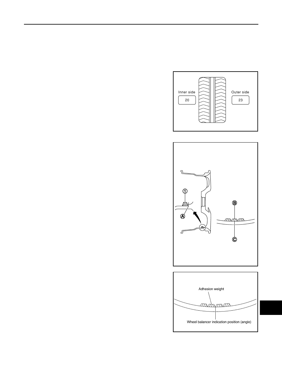
When inner and outer unbalance values are shown on the tire balance machine indicator, multiply outer
unbalance value by 5/3 to determine balance weight that should be used. Select the outer balance weight
with a value closest to the calculated value above and install to the designated outer position of, or at the
designated angle in relation to the road wheel.
CAUTION:
• Never install the inner balance weight before installing the outer balance weight.
• Before installing the balance weight, always to clean the mating surface of the road wheel.
a.
Indicated unbalance value
×
5/3 = balance weight to be installed
Calculation example:
23 g (0.81 oz)
×
5/3 = 38.33 g (1.35 oz)
⇒
37.5 g (1.32 oz) bal-
ance weight (closer to calculated balance weight value)
NOTE:
Note that balance weight value must be closer to the calculated
balance weight value.
Example:
36.2
⇒
35 g (1.23 oz)
36.3
⇒
37.5 g (1.32 oz)
b.
Installed balance weight in the position.
• When installing balance weight (1) to road wheels, set it into
the grooved area (A) on the inner wall of the road wheel as
shown in the figure so that the balance weight center (B) is
aligned with the tire balance machine indication position
(angle) (C).
CAUTION:
• Always use genuine NISSAN adhesion balance weights.
• Balance weights are non-reusable; always replace with
new ones.
• Never install more than three sheets of balance weight.
c.
If calculated balance weight value exceeds 50 g (1.76 oz), install
two balance weight sheets in line with each other as shown in
the figure.
CAUTION:
Never install one balance weight sheet on top of another.
3.
Start the tire balance machine again.
4.
Install drive-in balance weight on inner side of road wheel in the
tire balance machine indication position (angle).
CAUTION:
Never install more than two balance weight.
5.
Start the tire balance machine. Make sure that inner and outer
residual unbalance values are 5 g (0.17 oz) each or below.
6.
If either residual unbalance value exceeds 5 g (0.17 oz), repeat installation procedures.
SMA054D
JPEIC0040ZZ
PEIA0033E
MA-38
< PERIODIC MAINTENANCE >
CHASSIS MAINTENANCE
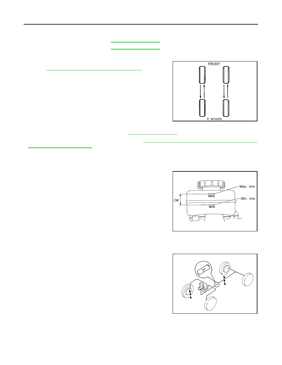
TIRE ROTATION
• Follow the maintenance schedule for tire rotation service intervals.
MA-5, "Explanation of General Maintenance"
• When installing the wheel, tighten wheel nuts to the specified
torque.
CAUTION:
• Never include the T-type spare tire when rotating the tires.
• When installing wheels, tighten them diagonally by dividing
the work two to three times in order to prevent the wheels
from developing any distortion.
• Be careful not to tighten wheel nut at torque exceeding the
criteria for preventing strain of disc rotor.
• Use NISSAN genuine wheel nuts for aluminum wheels.
• Perform the ID registration, after tire rotation. Refer to
WT-7, "ID REGISTRATION PROCEDURE : Transmit-
ter ID Registration Procedure"
BRAKE FLUID LEVEL AND LEAKS
BRAKE FLUID LEVEL AND LEAKS : Inspection
INFOID:0000000005248761
• If fluid level is extremely low, check brake system for leaks.
BRAKE LINES AND CABLES
BRAKE LINES AND CABLES : Inspection
INFOID:0000000005248762
• Check brake fluid lines and parking brake cables for improper
attachment, leaks, chafing, abrasions, deterioration, etc.
BRAKE FLUID
Limit
Dynamic (At flange):
Refer to
Static (At flange):
Wheel nuts tighting torque
: Refer to
SMA829C
SBR451D
SBR389C
CHASSIS MAINTENANCE
MA-39
< PERIODIC MAINTENANCE >
C
D
E
F
G
H
I
J
K
L
M
B
MA
N
O
A
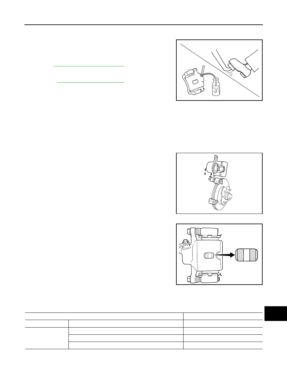
BRAKE FLUID : Changing
INFOID:0000000005248763
1.
Drain brake fluid from each bleed valve.
2.
Refill until new brake fluid comes out from each bleed valve.
Use same procedure as in bleeding hydraulic system to refill
brake fluid.
Refer to
BR-11, "Bleeding Brake System"
• Refill with recommended Genuine NISSAN Super Heavy Duty
Brake Fluid or equivalent DOT 3 (US FMVSS No. 116).
Refer to
MA-12, "Fluids and Lubricants"
• Never reuse drained brake fluid.
• Be careful not to splash brake fluid on painted areas.
DISC BRAKE
DISC BRAKE : Inspection
INFOID:0000000005248764
DISC ROTOR
Check condition, wear, and damage.
CALIPER
• Check for leakage.
BRAKE PAD
• Check for wear or damage.
DISC BRAKE : Front Disc Brake
INFOID:0000000005248765
2 PISTON TYPE
Unit: mm (in)
4 PISTON TYPE
SBR419C
SMA922A
BRA0010D
Item
Limit
Brake pad
Wear thickness
2.0 (0.079)
Disc rotor
Wear thickness
32.0 (1.260)
Thickness variation (measured at 8 positions)
0.015 (0.0006)
Runout (with it attached to the vehicle)
0.035 (0.0014)
Нет комментариевНе стесняйтесь поделиться с нами вашим ценным мнением.
Текст