Infiniti FX35, FX50 (S51). Manual — part 543
DIAGNOSIS AND REPAIR WORK FLOW
DLN-7
< BASIC INSPECTION >
[TRANSFER: ETX13C]
C
E
F
G
H
I
J
K
L
M
A
B
DLN
N
O
P
BASIC INSPECTION
DIAGNOSIS AND REPAIR WORK FLOW
Work Flow
INFOID:0000000005249032
DETAILED FLOW
1.
INTERVIEW FROM THE CUSTOMER
Clarify customer complaints before inspection. First of all, reproduce symptoms, and understand them fully.
Ask customer about his/her complaints carefully. Check symptoms by driving vehicle with customer, if neces-
sary.
CAUTION:
Customers are not professional. Never guess easily like “maybe the customer means that...,” or
“maybe the customer mentions this symptom”.
>> GO TO 2.
2.
CHECK AWD WARNING LAMP
Start the engine and drive at 30 km/h (19 MPH) or more for approximately 1 minute.
Does AWD warning lamp turn ON?
YES
>> GO TO 3.
NO
>> GO TO 6.
3.
PERFORM SELF-DIAGNOSIS
With CONSULT-III
1.
Perform self-diagnosis for “ALL MODE AWD/4WD”.
2.
Check malfunction detected by self-diagnosis.
3.
Erase self-diagnostic results for “ALL MODE AWD/4WD”.
>> GO TO 4.
4.
CHECK TERMINALS AND HARNESS CONNECTORS
Check pin terminals for damage or loose connection with harness connector.
>> GO TO 5.
5.
CHECK SYMPTOM REPRODUCTION
With CONSULT-III
Perform DTC reproduction procedure for the error system.
Is any error detected?
YES
>> GO TO 2.
NO
>> GO TO 6.
6.
PERFORM SYMPTOM DIAGNOSIS
Perform the symptom diagnosis for each system.
Is any malfunction present?
YES
>> GO TO 2.
NO
>> GO TO 7.
7.
FINAL CHECK
With CONSULT-III
Check input/output signal standard of “ALL MODE AWD/4WD”.
Is the input/output the standard value?
YES
>> INSPECTION END
NO
>> GO TO 2.
DLN-8
< SYSTEM DESCRIPTION >
[TRANSFER: ETX13C]
AWD SYSTEM
SYSTEM DESCRIPTION
AWD SYSTEM
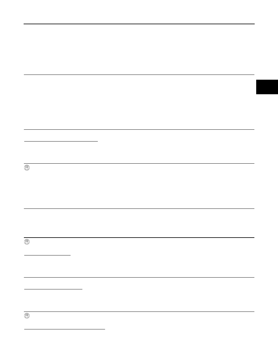
System Diagram
INFOID:0000000005249033
CONTROL DIAGRAM
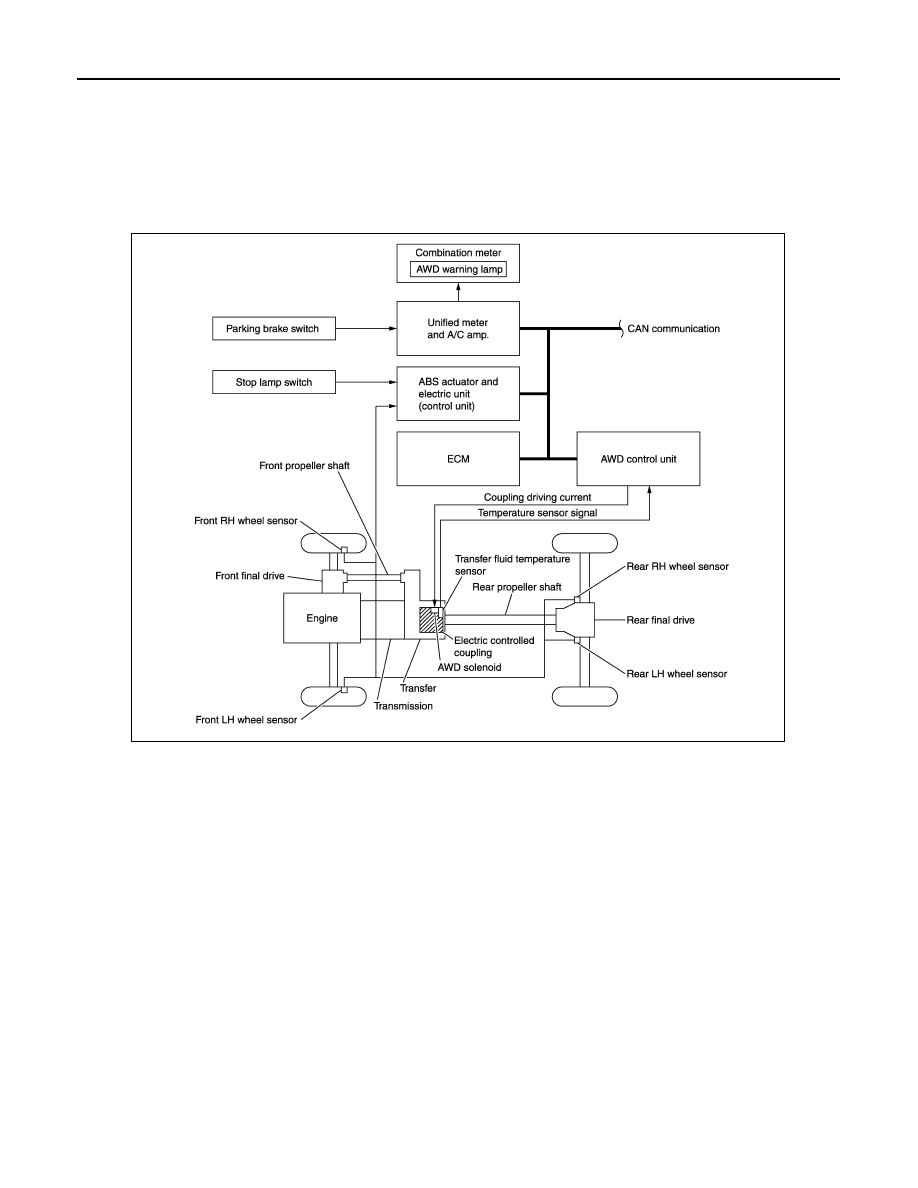
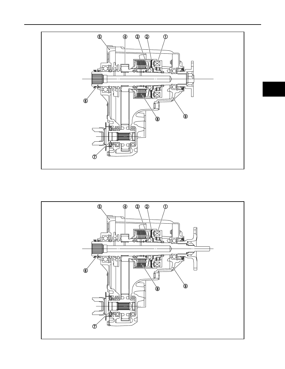
CROSS-SECTIONAL VIEW
JPDIE0103GB
AWD SYSTEM
DLN-9
< SYSTEM DESCRIPTION >
[TRANSFER: ETX13C]
C
E
F
G
H
I
J
K
L
M
A
B
DLN
N
O
P
VQ35HR
VK50VE
JSDIA0803ZZ
1.
Electromagnet
2.
Control clutch
3.
Cam
4.
Drive chain
5.
Front case
6.
Main shaft
7.
Front drive shaft
8.
Main clutch
9.
Rear case
JPDIE0102ZZ
1.
Electromagnet
2.
Control clutch
3.
Cam
DLN-10
< SYSTEM DESCRIPTION >
[TRANSFER: ETX13C]
AWD SYSTEM
System Description
INFOID:0000000005249034
DESCRIPTION
• Electronic control allows optimal distribution of torque to front/rear wheels to match road conditions.
• Makes possible stable driving, with no wheel spin, on snowy roads or other slippery surfaces.
• On roads which do not require AWD, it contributes to improved fuel economy by driving in conditions close to
rear-wheel drive.
• Sensor inputs determine the vehicle's turning condition, and in response tight cornering/braking are con-
trolled by distributing optimum torque to front wheels.
• It transmits/receives each signal from the following control unit via CAN communication line.
NOTE:
• When driving, if there is a large difference between front and rear wheel speed which continues for a long
time, fluid temperature of drive system parts becomes too high and AWD warning lamp blinks quickly. (When
AWD warning lamp blinks, vehicle changes to rear-wheel drive conditions.) Also, optional distribution of
torque sometimes becomes rigid before lamp blinks quickly, but it is not a malfunction.
• If AWD warning lamp is blinking quickly, stop vehicle and allow it to idle for some time. Blinking will stop and
AWD system will be restored.
• When driving, AWD warning lamp may blink slowly if there is a significant difference in diameter of the tires.
At this time, vehicle performance is not fully available and cautious driving is required. (Continues until the
engine is turned OFF.)
• If the warning lamp blinks slowly during driving but remains OFF after the engine is restarted, the system is
normal. If it again blinks slowly after driving for some time, vehicle must be inspected.
• When there is a difference of revolution speed between the front and rear wheel the shift occasionally
changes to direct 4-wheel driving conditions automatically. This is not a malfunction.
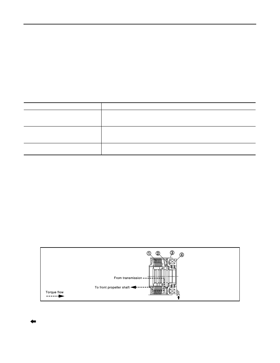
OPERATION PRINCIPLE
ELECTRIC CONTROLLED COUPLING
1.
AWD control unit supplies command current to electric controlled coupling (AWD solenoid).
2.
Control clutch is engaged by electromagnet and torque is detected in control clutch.
3.
The cam operates in response to control clutch torque and applies pressure to main clutch.
4.
Drive chain
5.
Front case
6.
Main shaft
7.
Front drive shaft
8.
Main clutch
9.
Rear case
Component parts
Function
ABS actuator and electric unit (control unit)
Transmits the following signals via CAN communication to AWD control unit.
• Vehicle speed signal
• Stop lamp switch signal (brake signal)
ECM
Transmits the following signals via CAN communication to AWD control unit.
• Accelerator pedal position signal
• Engine speed signal
Unified meter and A/C amp.
Transmits conditions of parking brake switch via CAN communication to AWD control
unit.
JPDIE0095GB
1.
Main clutch
2.
Control clutch
3.
Cam
4.
Electromagnet
: Current commanded from AWD control unit.
Нет комментариевНе стесняйтесь поделиться с нами вашим ценным мнением.
Текст