Infiniti FX35, FX50 (S51). Manual — part 1185

ECM
HAC-137
< ECU DIAGNOSIS INFORMATION >
[AUTOMATIC AIR CONDITIONER]
C
D
E
F
G
H
J
K
L
M
A
B
HAC
N
O
P
102
(SB)
111
(V)
ICC steering switch
Input
[Ignition switch: ON]
• ICC steering switch: OFF
4.2 V
[Ignition switch: ON]
• MAIN switch: Pressed
0 V
[Ignition switch: ON]
• CANCEL switch: Pressed
1.9 V
[Ignition switch: ON]
• RESUME/ACCELERATE switch:
Pressed
3.7 V
[Ignition switch: ON]
• SET/COAST switch: Pressed
3.2 V
[Ignition switch: ON]
• DISTANCE switch: Pressed
2.6 V
[Ignition switch: ON]
• LDP switch: Pressed
1.0 V
104
(R)
119
(W)
Accelerator pedal position
sensor 1
Input
[Ignition switch: ON]
• Engine: Stopped
• Accelerator pedal: Fully released
0.45 - 1.0 V
[Ignition switch: ON]
• Engine: Stopped
• Accelerator pedal: Fully depressed
4.4 - 4.8 V
105
(L)
—
CAN communication line
Input/
Output
—
—
106
(L)
128
(B)
Ignition switch
Input
[Ignition switch: OFF]
0 V
[Ignition switch: ON]
BATTERY VOLTAGE
(11 - 14 V)
108
(Y)*
3
(P)*
4
115
(GR)
Accelerator pedal position
sensor 2
Input
[Ignition switch: ON]
• Engine: Stopped
• Accelerator pedal: Fully released
0.22 - 0.5 V
[Ignition switch: ON]
• Engine: Stopped
• Accelerator pedal: Fully depressed
2.1 - 2.5 V
110
(P)
128
(B)
Stop lamp switch
Input
[Ignition switch: OFF]
• Brake pedal: Fully released
0 V
[Ignition switch: OFF]
• Brake pedal: Slightly depressed
BATTERY VOLTAGE
(11 - 14 V)
111
(V)
—
Sensor ground
(ASCD steering switch)
—
—
—
112
(LG)
128
(B)
Fuel pump control module
(FPCM) check
Input
[When cranking engine]
0 V
[Engine is running]
• Warm-up condition
• Idle speed
4 - 6 V
114
(GR)
—
Data link connector
Input/
Output
—
—
115
(BR)*
3
(GR)*
4
—
Sensor ground
(Accelerator pedal position
sensor 2)
—
—
—
Terminal No.
(Wire color)
Description
Condition
Value
(Approx.)
+
–
Signal name
Input/
Output

HAC-138
< ECU DIAGNOSIS INFORMATION >
[AUTOMATIC AIR CONDITIONER]
ECM
: Average voltage for pulse signal (Actual pulse signal can be confirmed by oscilloscope.)
*1: This may vary depending on internal resistance of the tester.
**2: Before measuring the terminal voltage, confirm that the battery is fully charged. Refer to
.
*3: Models with ICC
*4: Models with ASCD
116
(G)
128
(B)
PNP switch
Input
[Ignition switch: ON]
• Selector lever: P or N position
BATTERY VOLTAGE
(11 - 14 V)
[Ignition switch: ON]
• Selector lever: Except above posi-
tion
0 V
117
(BR)
128
(B)
ASCD brake switch
Input
[Ignition switch: ON]
• Brake pedal: Slightly depressed
0 V
[Ignition switch: ON]
• Brake pedal: Fully released
BATTERY VOLTAGE
(11 - 14 V)
118
(R)
128
(B)
Power supply for ECM
(Back-up)
Input
[Ignition switch: OFF]
BATTERY VOLTAGE
(11 - 14 V)
119
(W)
—
Sensor ground
(Accelerator pedal position
sensor 1)
—
—
—
120
(W)
128
(B)
Fuel tank temperature sensor
Input
[Engine is running]
0 - 4.8 V
Output voltage varies with fuel
tank temperature.
121
(GR)
128
(B)
Power supply for ECM
Input
[Ignition switch: ON]
BATTERY VOLTAGE
(11 - 14 V)
123
(B)
—
ECM ground
—
—
—
125
(R)
128
(B)
Fuel pump control module
(FPCM)
Output
[When cranking engine]
0 - 0.5 V
[Engine is running]
• Warm-up condition
• Idle speed
8 - 12 V
127
(LG)
128
(B)
EVAP canister vent control
valve
Output
[Ignition switch: ON]
BATTERY VOLTAGE
(11 - 14 V)
128
(B)
—
ECM ground
—
—
—
Terminal No.
(Wire color)
Description
Condition
Value
(Approx.)
+
–
Signal name
Input/
Output
UNIFIED METER AND A/C AMP.
HAC-139
< ECU DIAGNOSIS INFORMATION >
[AUTOMATIC AIR CONDITIONER]
C
D
E
F
G
H
J
K
L
M
A
B
HAC
N
O
P
UNIFIED METER AND A/C AMP.
Reference Value
INFOID:0000000005601970
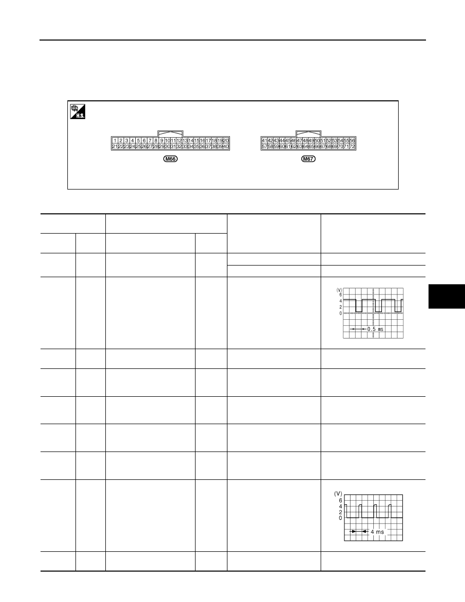
TERMINAL LAYOUT
PHYSICAL VALUES
JSIIA0097ZZ
Terminal No.
(Wire color)
Description
Condition
Value
(Approx.)
+
−
Signal name
Input/
Output
20
*
(L)
Ground
ION ON/OFF signal
Output
Blower fan: ON
0 V
Blower fan: OFF
12 V
38
(L)
Ground
Blower motor control signal
Output
• Ignition switch ON
• Blower speed: 1st speed
(manual)
41
(V)
Ground
ACC power supply
—
Ignition switch ACC
Battery voltage
43
(R)
Ground
Intake sensor signal
Input
Ignition switch ON
0 – 4.8 V
Output voltage varies with intake
temperature.
44
(LG)
Ground
In-vehicle sensor signal
Input
Ignition switch ON
0 – 4.8 V
Output voltage varies with in-vehi-
cle temperature.
45
(P)
Ground
Ambient sensor signal
Input
Ignition switch ON
0 – 4.8 V
Output voltage varies with ambient
temperature.
46
(O)
Ground
Sunload sensor signal
Input
Ignition switch ON
0 – 4.8 V
Output voltage varies with amount
of sunload.
47
*
(V)
Ground
Gas sensor signal
Input
NOTE:
The signal is different by mea-
surement environment of a ve-
hicle
53
(G)
Ground
IGN power supply
—
Ignition switch ON
Battery voltage
JSIIA0096ZZ
ZJIA1163J

HAC-140
< ECU DIAGNOSIS INFORMATION >
[AUTOMATIC AIR CONDITIONER]
UNIFIED METER AND A/C AMP.
*: With advanced climate control system (ACCS)
*: Unified meter and A/C amp. is not used for control.
54
(O)
Ground
BAT power supply
—
Ignition switch OFF
Battery voltage
55
(B)
Ground
Ground
—
Ignition switch ON
0 V
56
(L)
Ground
CAN-H
—
—
—
59
(GR)
Ground
Intake sensor ground
—
Ignition switch ON
0 V
60
(L)
Ground
In-vehicle sensor ground
—
Ignition switch ON
0 V
61
(BR)
Ground
Ambient sensor ground
—
Ignition switch ON
0 V
62
(SB)
Ground
Sunload sensor ground
—
Ignition switch ON
0 V
63
*
(R)
Ground
—
—
—
—
65
(O)
Ground
ECV (Electrical Control
Valve) signal
Output
• Ignition switch ON
• Self-diagnosis. STEP-4
(Code No. 45)
69
(L)
Ground
A/C LAN signal
Input/
Output
Ignition switch ON
70
(R)
Ground
Each door motor power sup-
ply
Output
Ignition switch ON
12 V
71
(B)
Ground
Ground
—
Ignition switch ON
0 V
72
(P)
Ground
CAN-L
—
—
—
Terminal No.
(Wire color)
Description
Condition
Value
(Approx.)
+
−
Signal name
Input/
Output
SJIA1607E
SJIA1453J
Нет комментариевНе стесняйтесь поделиться с нами вашим ценным мнением.
Текст