Infiniti FX35, FX50 (S51). Manual — part 559

FRONT CASE AND REAR CASE
DLN-71
< UNIT DISASSEMBLY AND ASSEMBLY >
[TRANSFER: ETX13C]
C
E
F
G
H
I
J
K
L
M
A
B
DLN
N
O
P
10. Remove front case and rear case fixing bolts, then remove har-
ness bracket.
*: With harness bracket.
11. Remove front case (1) from rear case by levering it up with a
suitable tool.
CAUTION:
Never damage the mating surface.
12. Remove snap ring (1) from front case.
13. Remove main shaft bearing from front case.
CAUTION:
Never use tools. Always remove by hand.
14. Remove snap ring (1) from main shaft.
Bolts symbol
Quantity
A
14
T (TORX bolt)
1
JPDIE0108ZZ
JPDIE0140ZZ
JPDIE0109ZZ
JPDIE0122ZZ
DLN-72
< UNIT DISASSEMBLY AND ASSEMBLY >
[TRANSFER: ETX13C]
FRONT CASE AND REAR CASE
15. Remove spacer (1) and steel ball (2) from main shaft.
CAUTION:
Be careful not to drop the steel ball.
16. Remove Oil pump from main shaft.
17. Remove drive chain and front drive shaft.
CAUTION:
Never use tools. Always remove by hand.
18. Remove transfer fluid temperature sensor bolt from rear case.
And then, remove transfer fluid temperature sensor (1).
19. Remove oil cover bolts from rear case. And then, remove oil
cover (1).
20. Remove retainer from AWD solenoid harness connector.
21. Remove AWD solenoid harness connector from rear case.
22. Remove O-ring from AWD solenoid harness connector.
23. Remove main shaft assembly from rear case with the drift (A)
[SST: ST33052000 (
—
)].
24. Remove snap ring (1) from rear case.
25. Remove rear bearing from rear case.
CAUTION:
Never use tools. Always remove by hand.
JPDIE0123ZZ
JPDIE0198ZZ
JPDIE0197ZZ
JPDIE0114ZZ
JPDIE0111ZZ
FRONT CASE AND REAR CASE
DLN-73
< UNIT DISASSEMBLY AND ASSEMBLY >
[TRANSFER: ETX13C]
C
E
F
G
H
I
J
K
L
M
A
B
DLN
N
O
P
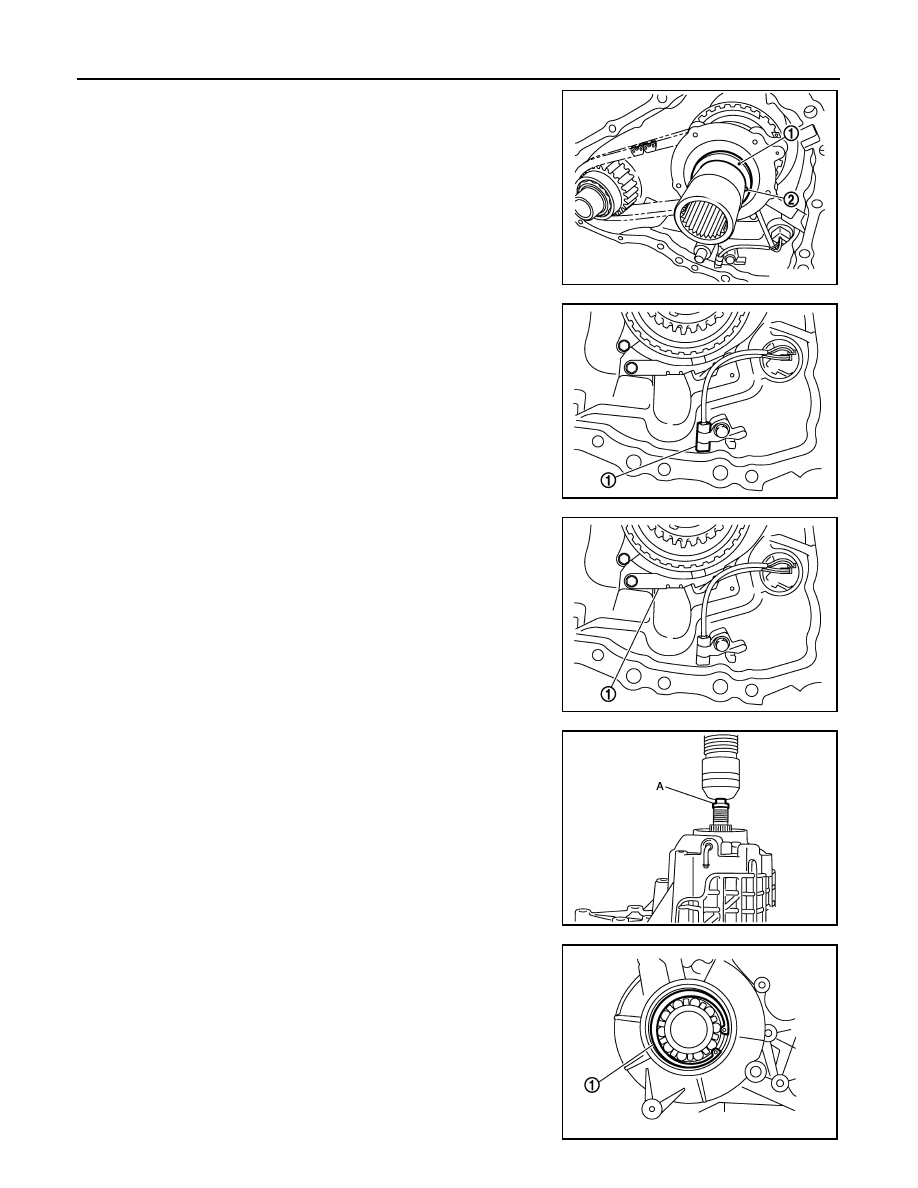
26. Remove baffle plate (1) from rear case.
27. Remove breather tube from rear case.
VQ35HR : Assembly
INFOID:0000000005249119
1.
Install breather tube to rear case within the angle (A) shown as follows.
Install rear oil seal to rear case with the drifts within the dimen-
sion (L) shown as follows.
CAUTION:
Never reuse breather tube.
2.
Install baffle plate to rear case.
3.
Install rear bearing to rear case.
CAUTION:
Never use tools. Always install by hand.
4.
Install snap ring (1) to rear case.
CAUTION:
Never reuse snap ring.
5.
Install main shaft assembly to rear case with the drift (A) [SST:
ST35321000 (
—
)].
CAUTION:
Apply transfer fluid to the sliding surface of main shaft and
needle bearing.
6.
Install O-ring to AWD solenoid harness connector.
CAUTION:
• Never reuse O-ring.
• Apply transfer fluid to O-ring.
7.
Install AWD solenoid harness connector into rear case.
8.
Install retainer to AWD solenoid harness connector.
JPDIE0112ZZ
Angle (A)
: 80 – 100
°
JPDIE0113ZZ
JPDIE0111ZZ
JPDIE0115ZZ
DLN-74
< UNIT DISASSEMBLY AND ASSEMBLY >
[TRANSFER: ETX13C]
FRONT CASE AND REAR CASE
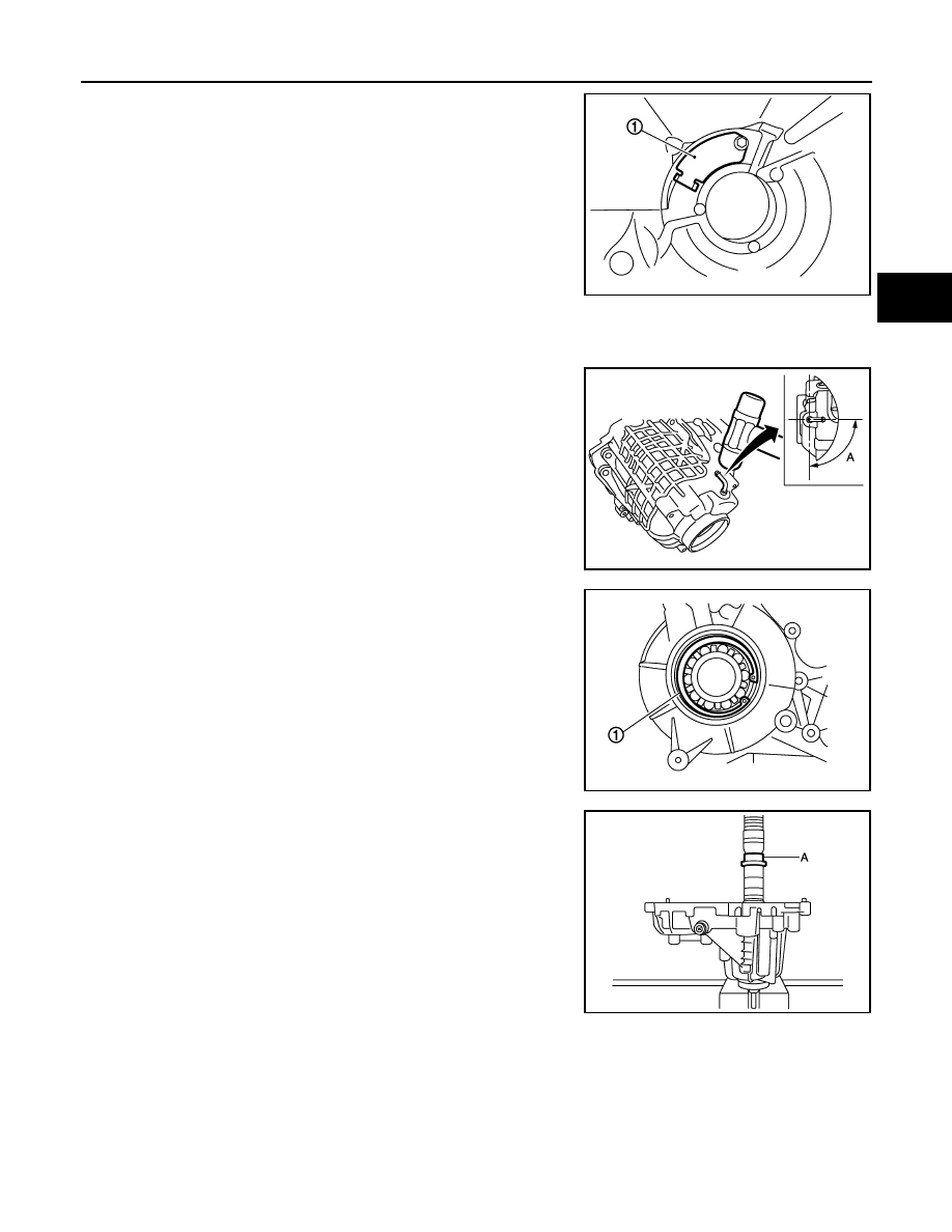
9.
Hold electric controlled coupling harness (1) with oil cover hold
plate (2), install oil cover (3) to rear case (4).
10. Install transfer fluid temperature sensor (1) to rear case.
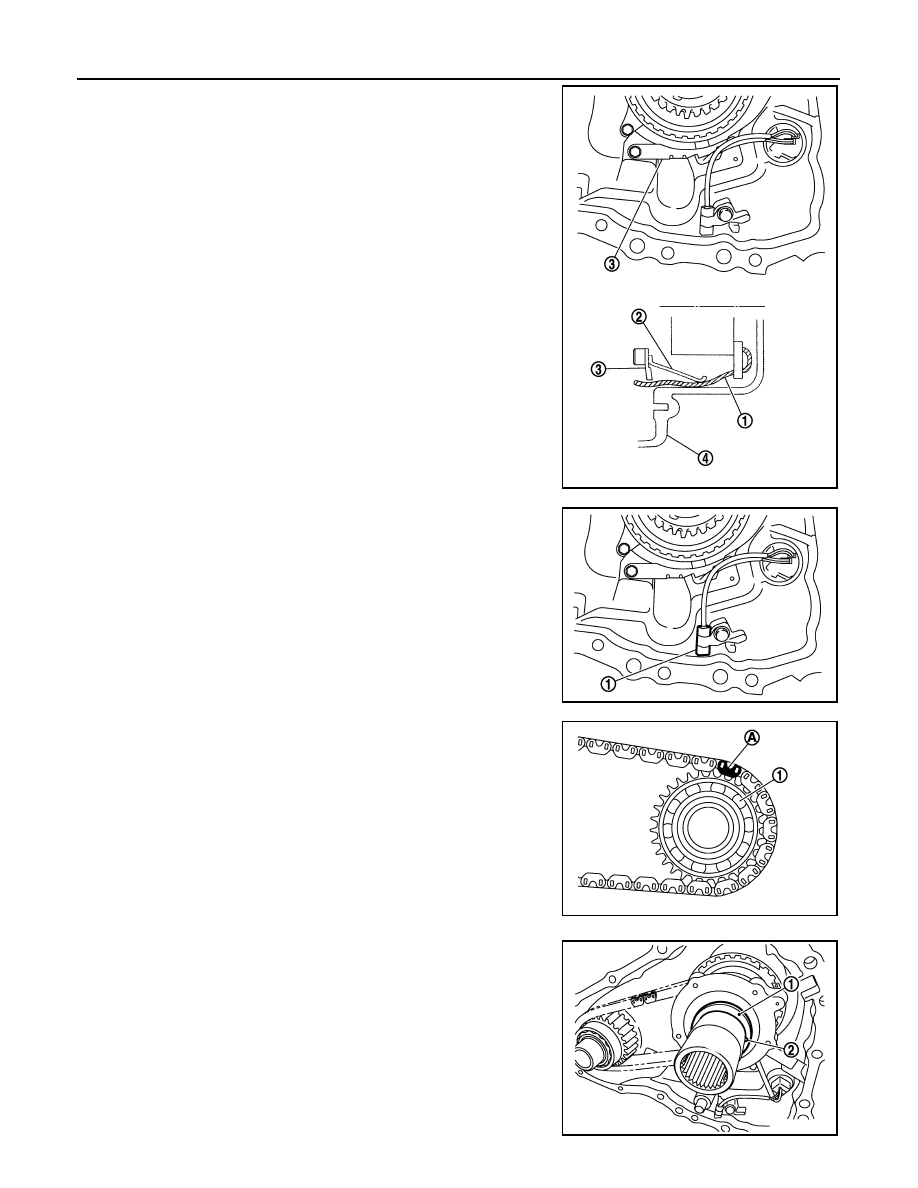
11. Set drive chain to front drive shaft.
CAUTION:
Identification mark (A) of drive chain should be in the side
of front bearing (1) of front drive shaft.
12. Install drive chain to main shaft, and then install front drive shaft.
CAUTION:
Never use tools. Always install by hand.
13. Install main shaft bearing to front case.
CAUTION:
Never use tools. Always install by hand.
14. Install oil pump to main shaft.
15. Install spacer (1) and steel ball (2) to main shaft.
JPDIE0199ZZ
JPDIE0198ZZ
JPDIE0075ZZ
JPDIE0123ZZ
Нет комментариевНе стесняйтесь поделиться с нами вашим ценным мнением.
Текст