Infiniti FX35, FX50 (S51). Manual — part 1412
PCS-6
< SYSTEM DESCRIPTION >
[IPDM E/R]
RELAY CONTROL SYSTEM
1.
IPDM E/R
A.
Engine room dash panel (RH)
PCS
POWER CONTROL SYSTEM
PCS-7
< SYSTEM DESCRIPTION >
[IPDM E/R]
C
D
E
F
G
H
I
J
K
L
B
A
O
P
N
POWER CONTROL SYSTEM
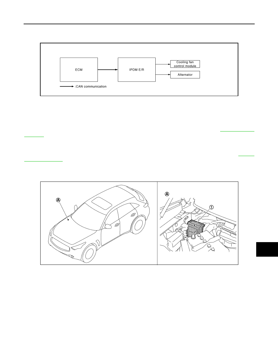
System Diagram
INFOID:0000000005240629
System Description
INFOID:0000000005240630
COOLING FAN CONTROL
IPDM E/R outputs pulse duty signal (PWM signal) to the cooling fan control module according to the status of
the cooling fan speed request signal received from ECM via CAN communication. Refer to
.
ALTERNATOR CONTROL
IPDM E/R outputs power generation command signal (PWM signal) to the alternator according to the status of
the power generation command value signal received from ECM via CAN communication. Refer to
.
Component Parts Location
INFOID:0000000005240631
JSMIA0004GB
1.
IPDM E/R
A.
Engine room dash panel (RH)
JPMIA1089ZZ
PCS-8
< SYSTEM DESCRIPTION >
[IPDM E/R]
SIGNAL BUFFER SYSTEM
SIGNAL BUFFER SYSTEM
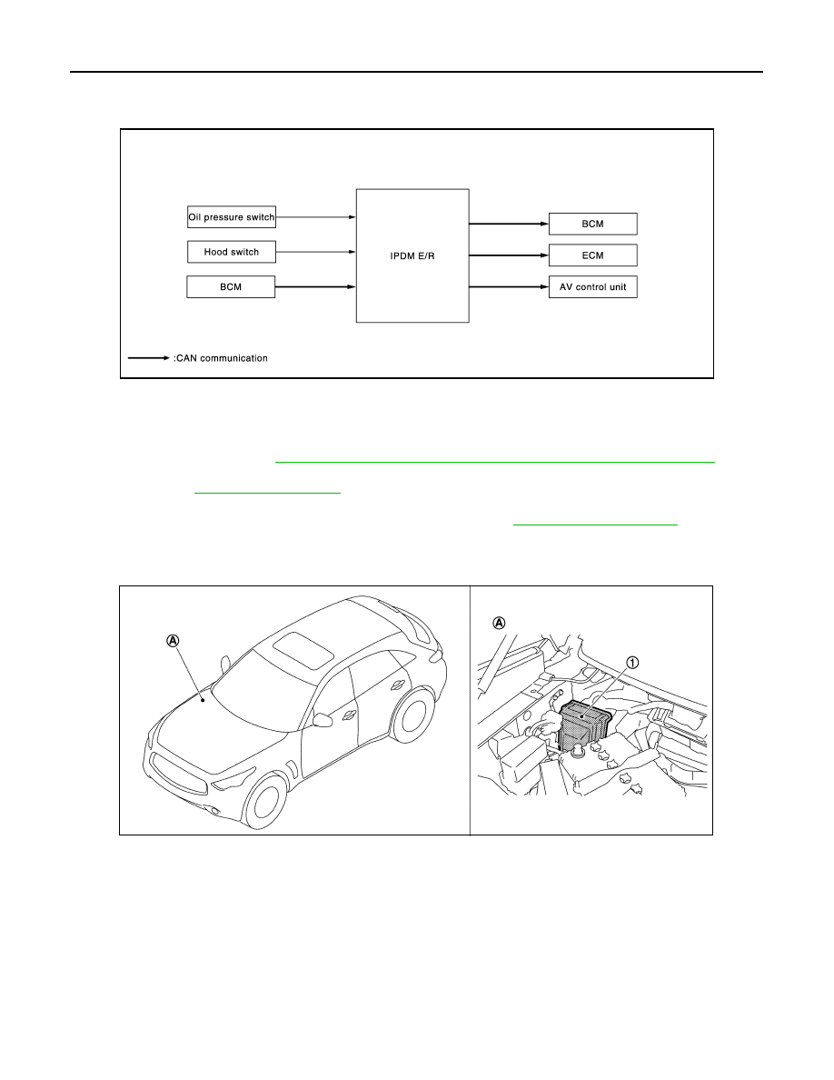
System Diagram
INFOID:0000000005240632
System Description
INFOID:0000000005240633
• IPDM E/R reads the status of the oil pressure switch and transmits the oil pressure switch signal to BCM via
CAN communication. Refer to
MWI-25, "WARNING LAMPS/INDICATOR LAMPS : System Diagram"
• IPDM E/R reads the status of the hood switch and transmits the hood switch signal to BCM via CAN commu-
• IPDM E/R receives the rear window defogger control signal from BCM via CAN communication and trans-
mits it to ECM and AV control unit via CAN communication. Refer to
.
Component Parts Location
INFOID:0000000005240634
JPMIA0952GB
1.
IPDM E/R
A.
Engine room dash panel (RH)
JPMIA1089ZZ
PCS
POWER CONSUMPTION CONTROL SYSTEM
PCS-9
< SYSTEM DESCRIPTION >
[IPDM E/R]
C
D
E
F
G
H
I
J
K
L
B
A
O
P
N
POWER CONSUMPTION CONTROL SYSTEM
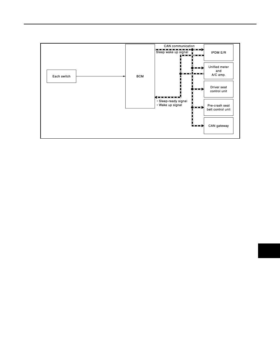
System Diagram
INFOID:0000000005688775
System Description
INFOID:0000000005240636
OUTLINE
• IPDM E/R incorporates a power consumption control function that reduces the power consumption accord-
ing to the vehicle status.
• IPDM E/R changes its status (control mode) with the sleep wake up signal received from BCM via CAN com-
munication.
Normal mode (wake-up)
- CAN communication is normally performed with other control units.
- Individual unit control by IPDM E/R is normally performed.
Low power consumption mode (sleep)
- Low power consumption control is active.
- CAN transmission is stopped.
SLEEP MODE ACTIVATION
• IPDM E/R judges that the sleep-ready conditions are fulfilled when the ignition switch is OFF and none of the
conditions below are present. Then it transmits a sleep-ready signal (ready) to BCM via CAN communica-
tion.
- Outputting signals to actuators
- Switches or relays operating
- Hood switch status is kept 50 ms or less.
- Output requests are being received from control units via CAN communication.
• IPDM E/R stops CAN communication and enters the low power consumption mode when it receives a sleep
wake up signal (sleep) from BCM and the sleep-ready conditions are fulfilled.
WAKE-UP OPERATION
• IPDM E/R changes from the low power consumption mode to the normal mode when it receives a sleep
wake-up signal (wake up) from BCM or any of the following conditions is fulfilled. In addition, it transmits a
sleep-ready signal (not-ready) to BCM via CAN communication to report the CAN communication start.
- Ignition switch ON
- The hood switch status changes.
- An output request is received from a control unit via CAN communication.
JMMIA0296GB
Нет комментариевНе стесняйтесь поделиться с нами вашим ценным мнением.
Текст